Troubleshooting
Component-level Troubleshooting
5
5-71
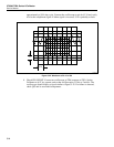
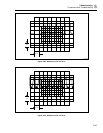
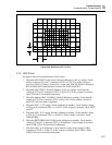
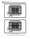
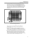
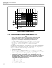
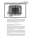
the input to the AC/DC sensor. The oscilloscope display should be switching
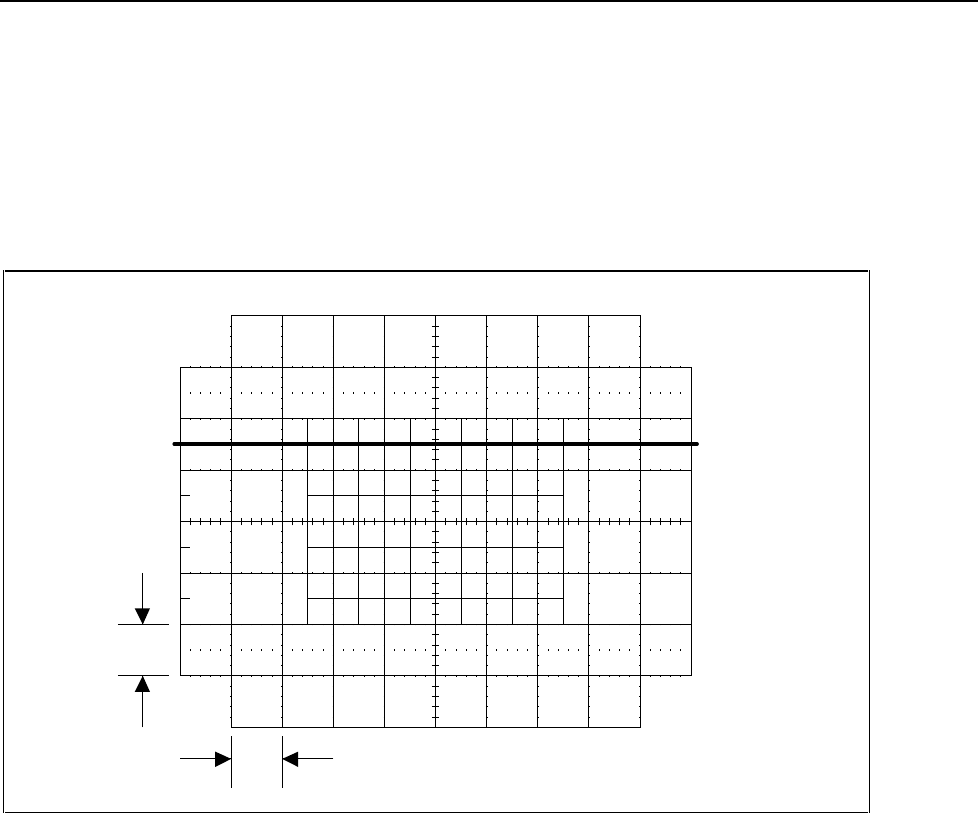
between Figure 5-29, which is the output of the DC SENSE BUFFER circuit and
Figure 5-30, which is the output of the AC SENSE BUFFER circuit. If either of
these signals is incorrect, check the appropriate SENSE BUFFER circuit as outlined
on the schematic. If these voltages are correct, set the Calibrator to 10.0V at 1 kHz,
operate, and verify the ac amplitude from the AC SENSE BUFFER remains the
same. If a failure is detected, check relay K4 and resistor Z3 in the AC SENSE
BUFFER circuit.
1 V
10 ms
F5-29.EPS
Figure 5-29. DC Sense Buffer Waveform TP6
Note
Before proceeding remove the jumper connecting SDL to SCOM on this
Oscillator Control assembly and the jumper connecting TP9 to TP10 on
the DAC assembly.
9. Check the AC/DC THERMAL SENSOR & SQUARE ROOT AMP. Set the
Calibrator to 1.0V at 1 kHz, operate. Connect a DMM to TP7 (common to TP2)
which is the output of the Fluke RMS Sensor. The DMM should read 3.16V dc ±160
mV. If this voltage is incorrect, check U14, U15, U17, and associated components.
10. Check the RCL ANALOG SWITCHING circuit. Set the Calibrator to 1.0V at 1 kHz,
operate. Connect a DMM to TP8 (common to TP2) which is the RCL line. The
DMM should read the same voltage at TP7 in the previous step. If this voltage is
incorrect, check U19A, K6, and their drive circuitry. Set the Calibrator to 5V at 1
kHz, operate. The DMM connect to TP8 should read 1.58V ±160 mV. If this voltage
is incorrect, check U31, U19B, K7, and their appropriate drive circuit.


