


5700A/5720A Series II Calibrator
Service Manual
2-112
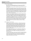
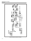
2-171. Ohms Main Assembly Support of Current Function Calibration
To calibrate the current function, the Current assembly routes output current to the Ohms
Main assembly, where it is connected through a resistance. Current is determined by
measuring the voltage across this resistance. During calibration, half of K38 connects
DAC OUT LO to the SENSE LO side of the 1x10
n
string (Z1 pin 6). The Current
assembly generates approximately 60 µA of current on the DAC OUT LO line, which
can cause an error during measurement. To prevent this error, half of relay K38 connects
the -17S supply through R6 to the DAC OUT LO line. This generates an opposite-
polarity 60 µA current to cancel the current from the Current assembly.
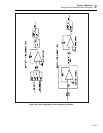
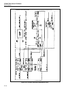
2-172. Ohms Digital Control
The Ohms Main assembly is digitally controlled by the 82C55 Programmable Peripheral
Interface IC on the Ohms Cal assembly. This IC, under system software control through
the guarded digital bus, has three ports generating 24 outputs. PA0-PA7 of port A, PB0-
PB3 of port B, and PC0-PC4 of port C are routed on the motherboard to the Ohms Main
assembly. These lines and two decoders in U9 and U10 control nine relay driver ICs,
which in turn control 39 Ohms relays. Relay driver U3 drives non-latching relays K5,
K6, K8, K11, K12 and K38. Relay drivers U2, U5-U8, and U11-U13 drive the latching
relays.
Port A (PA0-PA7) is a common input bus for all relay drivers. IC U9 decodes PB0-PB3
to strobe the latching relay drivers. This signal causes the contents of the data on the
input bus to be latched into the latch portion of the selected device. IC U10 decodes
PC0-PC3 to provide four enable lines. Each line goes to two latch/drivers and when true
(0V), drives the relay coils on or off according to the contents of the latch. Since these
are latching relays, they are pulsed only briefly. The latching relays each have two coils,
one to set the relay and one to reset it. When the ohms function is not being used, all
relays are set, as shown on the schematic.
PC4 is the strobe line for non-latching relay driver U3. The enable is connected to LH
COM so the relays receive constant drive. These non-latching reed relays are shown in
the non-energized state.
2-173. Ohms Cal Assembly (A9)
The Ohms Cal assembly (A9) contains the 1Ω, 1.9Ω, and short resistance values. It also
contains a digital control circuit, and a two-wire compensation circuit to allow accurate
calibration of two-wire ohmmeters. A differential amplifier circuit and a 2/5/10V source
circuit are used during calibration of the ohms function.
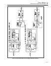
2-174. Ohms CAL Digital Control
The heart of the Ohms Cal assembly digital control circuit is the 82C55 Programmable
Peripheral Interface IC (U11) mentioned previously under "Digital Control". This IC has
three ports generating 24 outputs. These outputs control seven 5801 latching relay
drivers ICs (U14-U20), a 4051 analog multiplexer (U21) for self diagnostics, and several
FET switches.
Port A (PA0-PA7) is a common input bus for latching relay drivers and multiplexer U21.
These lines also go to the Ohms Main assembly as previously described to control relay
drivers there.
Lines PB0-PB3 of port B goes to decoder U12 (PB3 is inverted by U22) and to the Ohms
Main assembly. The output of U12 strobes latch/driver ICs to latch data on input bus
lines.