


5700A/5720A Series II Calibrator
Service Manual
2-28
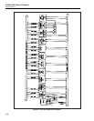
2-46. Front Panel Assembly (A2)
The Front Panel assembly, operating in conjunction with the Keyboard assembly (linked
by a cable), is the operator interface to the Calibrator. This assembly contains two
separate vacuum-fluorescent displays: the Control Display and the Output Display. Each
display has its own control, high voltage drive, and filament-switching circuits. This
assembly also contains clock regeneration, refresh failure detect, keyboard scanner,
rotary knob encoder, LED drive, and decoding and timing circuitry.
Connector J2 connects this assembly with the Keyboard/Encoder. Connector J1
interfaces with the CPU assembly and the Digital Power Supply assembly via the Digital
Motherboard.
2-47. Clock Regeneration Circuitry
To minimize EMI (electro-magnetic interference), the Front Panel assembly accepts a
low-level sine-wave (approximately 200 mV p-p) 3.6864 MHz clock from the CPU
assembly and converts it to a TTL-acceptable level. This is done by high-speed
differential comparator (U7A), operating on incoming signals 3.6864MHZCLK and
3.6864MHZCLK*. The output of U7A is the input to U8 and is also inverted by U11B to
create the 3.6864 MHz clock signal CLOCK. Twelve-stage binary counter U8 divides
the 3.6864 MHz clock by eight and U11A inverts the signal to create 460.8 kHz. The
master clock is further divided by U8, which outputs a 900 Hz signal on pin 1. These
clocks provide system timing for the other ICs on the assembly. A -5.2V supply for U7
is provided by VR5, with C64 acting as the supply bypass.
2-48. Refresh Failure Detect Circuitry
If a clock failure were to occur, the refresh cycles of the vacuum-fluorescent displays
would be interrupted. This condition could damage the tubes if not immediately
detected. Refresh failure detect circuitry monitors the GRIDDATA output from the last
high voltage driver (U23) for the Control Display. This output (REFRESH) is used to
clear a watchdog timer (U6) every refresh cycle. If the refresh is interrupted and
GRIDDATA does not occur, the watchdog timer times out and latches U12. Flip-flop
U12 generates control lines 75VSD and PSFAILINTR*. Control line 75VSD is routed to
the Digital Power Supply assembly to shut down the +35V and +75V power supplies,
thus preventing damage to the vacuum-fluorescent displays. Interrupt line
PSFAILINTR* is used by PLD U3 to properly blank the Control Display and Output
Display through DMDBLANK and OTDBLANK, and alerts the CPU that this failure
has occurred.
2-49. Decoding and Timing Circuitry
Main decoding and master timing functions for the front panel are accomplished by an
EP900 PLD (Programmable Logic Device), U3. Two state machines control display
refresh and filament switching. Filament switching is handled by two non-overlapping
57.6 kHz signals.
Signals GSTRBE and STROBE are master timing and synchronization signals used by
the other ICs. Signal DMDBLANK controls the Control Display grid drivers, ABCLK
and CDCLK control the Control Display anode drivers, and OTDBLANK controls the
Output Display grid and anode drivers. Front panel DTACK and interrupt functions, and
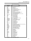
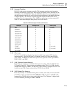
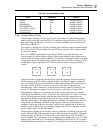
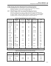
generation of the various chip select and reset signals are also provided by U3. Table 2-6
is a memory map for the front panel.