


5700A/5720A Series II Calibrator
Service Manual
3-46
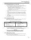
Note
If the spectrum analyzer input impedance is 50
Ω
, do not use a separate
termination.
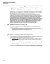
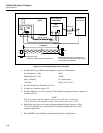
2. With 0 dBm output programmed from the Calibrator wideband output, select
frequencies over the band of 1 MHz to 30 MHz and verify that use the spectrum
analyzer to verify that any harmonics are below -40 dBm for fundamentals up to 10
MHz and below -34 dBm for fundamentals of 10 MHz and above.
3. Disconnect the equipment from the Calibrator.
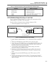
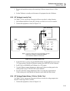
3-38. AC Voltage Overshoot Test
Proceed as follows to test for ac voltage overshoot:
1. Connect the Calibrator output to a properly compensated 10:1 probe.
2. AC couple the oscilloscope and set the sweeptime to a fairly low sweeptime
(approximately 1 sec/div).
3. Set the Calibrator to 7.07V at 1 kHz, and press OPR/STBY.
4. Set the scope vertical sensitivity for 0.05V/div. Offset the trace vertically until you
can see the top of the waveform at the approximate center of the display (must be at
least 2-3 divisions down from the top of the scope graticule).
5. Set the Calibrator to standby and then back to operate. Verify that any overshoot
visible on the oscilloscope display is less than 1.5 divisions (approximately 10% of
the peak value).
6. Repeat the test at 100 Hz and 100 kHz. This completes the Optional Tests.
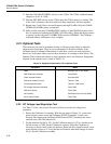
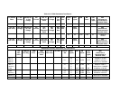
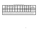
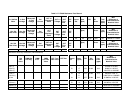
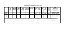
3-39. Minimum Use Requirements
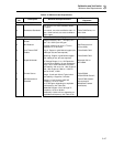
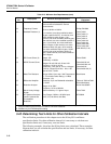
Table 3-15 defines specifications for test equipment needed for tests in this section of the
manual. If the specific test equipment called for in these tests is not available, you can
substitute equipment that meets these specifications.