


5700A/5720A Series II Calibrator
Service Manual
5-42
voltages of 3V, 1V, 300 mV, and 30 mV, all at 1 kHz, and verify the DMM read the
selected voltage ±5%. If a failure is detected, check K4-K8, Z1, and Z2. Next,
connect the supplied output cable and 50Ω terminator to the WIDEBAND connector
of the Calibrator front panel. Refer to the 5700A/5720A Series II Operators manual
and run Wideband Gain calibration. After the Wideband Gain calibration is complete
check the Wideband output at the end of the cable and 50Ω terminator at 3V, 1V,
300 mV, and 30 mV, all at 1 kHz, and verify the output is within 0.2%.
5-5. Troubleshooting the Wideband Oscillator Assembly (A6)
Proceed as follows to troubleshoot the Wideband Oscillator assembly (A5):
1. Remove the front and rear shields from the Wideband Oscillator assembly and place
it up on the extender card. Power up the Calibrator and call up the Wideband
function.
Note
All measurements are referenced to SCOM (TP16 or TP17) and all
Calibrator outputs are from the Wideband Option unless otherwise Noted.
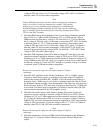
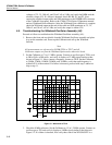
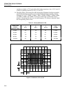
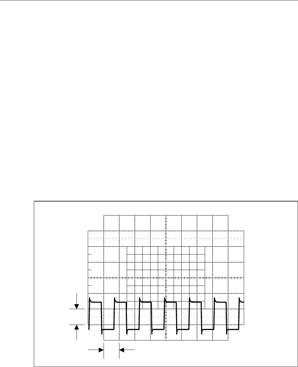
2. Set the Calibrator to 1V at 1.2 MHz, operate. Connect an oscilloscope to TP10, set it
to 500 mV/div at 500 ns/div, and verify it displays a1.2 MHz signal similar to that
shown in Figure 5-1. Next, connect a frequency counter to TP10. Set the Calibrator
to 2 MHz, 5 MHz, 10 MHz, 20 MHz, and 30 MHz, verify that each frequency is
within 0.01% of the nominal. If a failure is detected, proceed with step 3 otherwise
skip to step 11.
1 V
10 ms
F5-1.EPS
Figure 5-1. Waveform at TP10
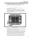
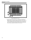
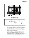
3. Check the 8 MHz reference. Set the Calibrator to 1V at 1.2 MHz operate. Connect an
oscilloscope to TP1 and verify it displays a 8 MHz signal similar to that shown in
Figure 5-2. If a failure is detected, first verify that control line WB ON/OFF* is a