


5700A/5720A Series II Calibrator
Service Manual
2-48
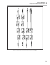
2-90. Switch Matrix Operation
:
2
.
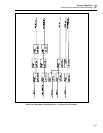
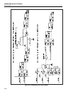
2V AC and 22V AC Ranges
Refer to Figure 2-9 for the following discussion. AC 2.2V and 22V ranges are generated
by the Oscillator assemblies and routed directly to the front panel binding posts through
relays located on the Switch Matrix and Motherboard.
Line OSC OUT is connected to INT OUT HI through relays K19A, K18B, K27, and
K30. INT OUT HI is connected to the OUTPUT HI binding post through relay K1 on the
motherboard. Line OSC SENSE is connected to INT SENSE HI through relays K19B,
K18A, K25, and K26. Motherboard relays K2 and K3 switch INT SENSE HI to the
SENSE HI binding post during external sensing, or OUTPUT/SENSE HI during internal
sensing.
Line OSC COM is connected to the OUTPUT LO binding post through relays K11 and
K10 on the Switch Matrix. Switch Matrix relays K13 and K15 connect OSC SENSE LO
to the SENSE LO binding post during external sensing, or OUTPUT/SENSE LO during
internal sensing.
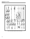
2-91. Switch Matrix Operation
:
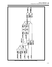
220V AC and DC Ranges
Refer to Figure 2-10 for the following discussion. In the dc 220V range, PA OUT HI
from the Power Amplifier assembly (A16) is routed to the High Voltage Control
assembly (A14), where it goes through relay K10 and becomes PA OUT DC. Line PA
OUT DC is routed to the Switch Matrix and connected to INT OUT HI through relays
K20, K19A, K18B, K27 and K30. Relay K1 on the motherboard connects INT OUT HI
to the OUTPUT HI binding post.
Line PA SENSE DC is connected to INT SENSE HI through relays K20, K19B, K18A,
K25, and K26. Motherboard relays K2 and K3 switch INT SENSE HI to the SENSE HI
binding post during external sensing, or OUT/SENSE HI during internal sensing. PA
COM and DAC LO are connected by relays K11 and K12, and connected to the
OUTPUT LO binding post by relay K10. Switch Matrix relays K14 and K15 connect R
COM to the SENSE LO binding post during external sensing, or OUTPUT/SENSE LO
during internal sensing.
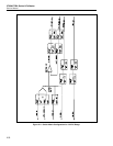
In the ac 220V range, Power Amplifier outputs PA OUT HI and PA SNS AC are routed
to the High Voltage Control assembly (A14) where relays K10, K3, and K13 connect
them to HV OUT and HV SNS respectively. HV OUT is connected to the OUTPUT HI
binding post through relays K9 and K1 on the motherboard. Motherboard relays K10,
K2, and K3 connect HV SNS to the SENSE HI binding post during external sensing, or
to OUTPUT/SENSE HI during internal sensing. Connection to the OUTPUT LO and
SENSE LO binding posts is done with relays on the Switch Matrix. PA COM is
connected to the OUTPUT LO binding post through relays K11 and K10. Switch Matrix
Relays K13 and K15 connected OSC SENSE LO to the SENSE LO binding post during
external sensing, or OUTPUT/SENSE LO during internal sensing.