


Troubleshooting
Component-level Troubleshooting
5
5-45
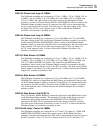
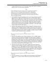
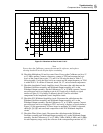
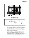
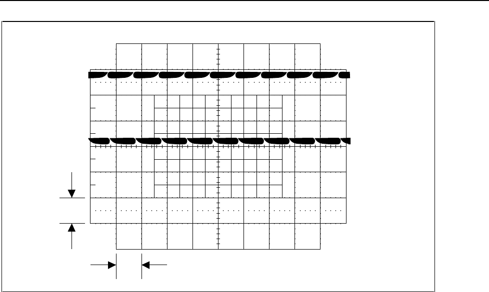
1 V
10 ms
F5-4.EPS
Figure 5-4. Waveform at Pins 14 and 15 of U1
Note
Power down the Calibrator, remove the external dc reference, and replace
shorting header E6 on the J6 pins before continuing.
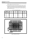
10. Check the Multiplexer U6 and its control lines. Power up the Calibrator and it to 1V
at 1.2 MHz, operate. Connect a frequency counter to TP10 and measure the logic
levels of the control lines at pins 7, 9, and 10 of U6 using the data in Table 5-1
following table. Verify the logic levels are correct and the output frequency at TP10
is within 0.01%. If a failure is detected, check U6, U7, and associated components.
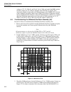
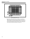
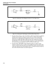
11. Check the Amplitude Control Amplifier circuit. Disconnect the cable between the
Wideband Oscillator assembly and Wideband Output assembly at J1 on the
Wideband Output assembly. Set the Calibrator to 1V at 1.2 MHz, operate. Connect
an oscilloscope set for ac coupling to pin 6 of U9 and verify it displays a signal
similar to Figure 5-5. If a failure is detected, check U9 and its associated
components in the Amplitude Control Amplifier circuit.
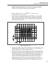
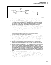
12. Check the X10 Wideband Amplifier circuit. Disconnect the cable between the
Wideband Oscillator assembly and Wideband Output assembly at J1 on the
Wideband Output assembly. Set the Calibrator to 1V at 1.2 MHz, operate. Connect
an oscilloscope set for ac coupling to TP13 and verify is displays a signal similar to
Figure 5-5, but approximately 10 times larger in amplitude. If a failure is detected,
check Q4, Q5, Q6, and associated components in the X10 Wideband Amplifier
circuit.
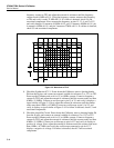
13. Check the Filter Select circuit. Disconnect the cable between the Wideband
Oscillator assembly and Wideband Output assembly at J1 on the Wideband Output
assembly. Set the Calibrator to 1V at 1.2 MHz, 2 Mhz, 4 MHz, 8 MHz, and 16 MHz.
At each frequency range verify the collector of the corresponding transistor in U13