Troubleshooting
Interpreting Diagnostic Fault Codes
5
5-29
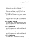
hybrid is warmed up and regulating. The heater voltage is measured to be 0.7V ±10%
±0.2V. A failure indicates the Power Amplifier assembly (A16) is probably at fault.
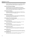
3521 Assembly A16 Is Not Responding
At power up the instrument checks to see what assemblies are not installed. This test
verifies that the Power Amplifier is not responding. A failure indicates the Power
Amplifier assembly (A16) is probably at fault.
3522 Spare
This fault code is not used.
3523 Spare
This fault code is not used.
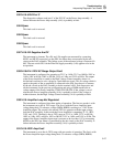
3524 A16: Power Amp Is Too Hot
The temperature of the Power Amp assembly is checked by connecting the output of the
Temperature Sensor (MUX4) to the SDL line where it is measured by the adc circuit on
the DAC assembly. This fault occurs if the measured voltage is over 1.7V. A failure
indicates the Power Amplifier assembly (A16) is probably at fault.
3525 220V DC Initialization Fault
This fault occurs if the diagnostics software was unable to properly set the Power
Amplifier assembly hardware for diagnostics testing. A failure indicates the Power
Amplifier assembly (A16) is probably at fault.
3526 220V AC Initialization Fault
This fault occurs if the diagnostics software was unable to properly se the Power
Amplifier assembly hardware for diagnostics testing in the AC mode. A failure indicates
the Power Amplifier assembly (A16) is probably at fault.
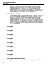
3527 A16: Power Amp DC Cal Network Zero Fault
The instrument is dormant. The offset of the 220V DC INT. CAL NETWORK circuit on
the Power Amplifier is measured by connecting its input to ACOM and the output is
connected to the RCL line. RCL is routed to the +input of the adc circuit on the DAC
assembly and the -input is connected to the DAC output which is adjusted until a null is
achieved. This fault occurs if the DAC assembly was unable to converge. A failure
indicates the Power Amplifier assembly (A16) is probably at fault.
3528 A16: Power Amp DC Cal Network Gain Fault
The instrument is dormant. The gain of the 220V INT. CAL NETWORK circuit on the
Power Amplifier is measured by connecting its input to the 13V reference (BRF13,
BSRF13) and the output is connected to the RCL line. RCL is routed to the +input of the
adc circuit on the DAC assembly and the -input is connected to the DAC output which is
adjusted until a null is achieved. This fault occurs if the nominal gain of 0.125 is over
7%. A failure indicates the Power Amplifier assembly (A16) is probably at fault.
3529 A16: Power Amp 220V Range Attenuator Fault
The Power Amplifier is configured to the dc 220V range with the input voltage being the
6.5V reference BRF6 and BSRF6. The resulting -130V at the output is connected to the


