


5700A/5720A Series II Calibrator
Service Manual
2-126
Internal calibration of the 2.2A range and gain of the High Voltage/High Current
assembly is discussed further in the theory for the High Voltage assemblies.
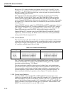
2-195. Current Guard Buffer
Buffer amplifier U4, configured as a voltage follower, is used to provide a guard voltage
equal to the output voltage across the external load. The guard voltage, if used, prevents
any output current from being shunted away from the load due to leakage or shunt
capacitance in the system cabling.
2-196. Compliance Limiter
A compliance limiter circuit consisting of Q24, Q25, and associated components clamps
the output to ±11V during an over-compliance condition.
2-197. Current/Compliance Voltage Monitor
The current/compliance voltage monitor circuit, which contains CMOS analog switch
U5A, U5C, U5D, op amp U6, and associated components, measures the voltage on either
side of the current shunts. This allows the Calibrator to detect an over-current or over-
compliance condition. A logic low on control line FET3 closes U5A to connect the
monitor circuit to the input side of the shunt resistor. The measurement at this point is
the sum of the output compliance voltage and voltage drop across the shunt, which is
proportional to the output current. A logic high on control line FET3 opens U5C, which
allows pull-down resistor R36 to close U5D. This connects the monitor circuit to the
output side of the shunt resistor, which gives the output compliance voltage.
Op amp U6 and associated components create an absolute value circuit whose output,
CUR/COMP MONITOR, is always a positive dc voltage. During operation in the ac
current function U6B generates a negative half-wave signal equal to the positive peaks of
its input. Resistors R31 and R30 sum this half-wave signal and the input signal at the
input of U6A. Capacitor C14 averages the voltage so the output of U6A is a dc voltage
which represents the average value of the selected input.
The diagnostic circuit connects CUR/COMP/ MONITOR to the SDL line, on which it is
routed to the DAC assembly (A11) to be measured by the adc circuit. The calibrator
software computes the difference between the two measurements and divides the result
by the shunt value to determine the output current.
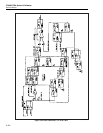
2-198. Current Assembly Calibration
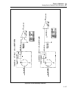
Refer to Figure 2-36 for the following discussion. Internal calibration of the Current
assembly is a process of determining the offset and gain constants for each of the four
current ranges.
To determine the offset of the 220 mA range, the Current assembly is set to the positive
dc 220 mA range with its input from the DAC assembly set to 0V. The output of the
Current assembly is routed to the Ohms Main assembly (A10), via INT OUT HI, where
it is connected to the previously calibrated 100Ω resistor.
To get a checkpoint reading, the Current assembly output is removed from the 100/Q
resistor on Ohms (via the output switching relays). The 100Ω resistor is connected to a
differential amplifier on the Ohms Cal assembly (A9). The output of this differential