


5700A/5720A Series II Calibrator
Service Manual
2-56
2-95. Switch Matrix Operation
:
220 mV AC Range
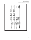
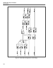
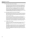
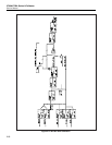
Refer to Figure 2-14 for the following discussion. As previously mentioned, the ac 220
mV range uses the same resistor network as the dc 220 mV range. In generating the ac
220 mV range the Oscillator assembly is set to the 2.2V range. Lines OSC OUT and
OSC SENSE are connected to pin 3 of the 10:1 divider by relays K5 and K6. Lines OS
COM and OSC SENSE LO are connected to pin 2 by relays K11 and K9 respectively.
This divided output from pin 1 is referred to as AC/DC mV on the schematic. The
AC/DC mV is then connected to INT SENSE HI through relay K17 on sheet 1 of the
Switch Matrix schematic. Signal INT SENSE HI is connected to the OUTPUT HI
binding post through relays K2 and K3 on the motherboard. Sensing for the LO occurs
by connecting OS COM and OSC SENSE LO via K11 and K9. A single line is run out to
the OUTPUT LO binding post by relay K33 on the Switch Matrix.
2-96. Switch Matrix Operation
:
2
.
2 mV and 22 mV AC Ranges
Refer to Figure 2-14 for the following discussion. The ac 2.2 mV and 22 mV ranges use
the 100:1 divider and the 10:1 divider of resistor network on 4HR1 for a total division of
1000:1. Switch Matrix operation for these two ranges is the same. For the 2.2 mV range,
the Oscillator assembly is set to the 2.2V range. For the 22 mV range, the Oscillator
assembly is set to the 22V range.
Signals OS COM and OSC SENSE LO are connected to pin 6 of the 100:1 divider and
pin 2 of the 10:1 divider by relays K11 and K9. OSC OUT and OSC SENSE are
connected to the input (pin 7) of the 100:1 divider by relay K3 (A and B). The output of
this 100:1 divider is then connected to the input of the 10:1 divider (pin 3) by relay K7.
At the output of the 10:1 divider (called AC/DC mV on the schematic) there is a total
division of 1000:1. Connection to the binding posts is done in the same manner as in the
ac 220 mV range. In all cases, the output impedance of the millivolt ranges is 50Ω.
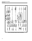
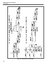
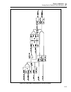
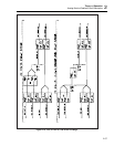
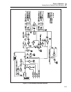
2-97. Calibration of the mV Ranges
Calibration of the mV ranges involves determining the resistor ratios of the 10:1 divider
and the 1000:1 divider (100:1 and 10:1 dividers cascaded). In addition, an offset
calibration is performed on the 10:1 divider to remove thermal EMF error for the 220
mV dc range.
Refer to Figure 2-15 for the following discussion. The 10:1 divider offset is calibrated by
configuring the Switch Matrix for the 220 mV dc range, except with the output of the
range (AC/DC mV) switched into the input of the internal cal amplifier through relays
K17 and K29. The Calibration procedure is the same as described for the 2.2V range
offset calibration except that during a checkpoint reading, control line PC4 turns on Q11
which connects SWM SENSE LO to the input of the zero amplifier, representing 0V for
the 220 mV range.