


Troubleshooting
Component-level Troubleshooting
5
5-47
5-6. Troubleshooting the Current/Hi-Res Assembly (A7)
The Current/Hi-Res assembly generates output current and contains the high-resolution
oscillator onto which the Oscillator Control assembly phase locks. Since these two
functions are independent except for their digital control, troubleshooting procedures for
each portion are presented separately.
5-7. Current Section
Proceed as follows to troubleshoot the current section of the Current/Hi-Res assembly
(A7):
1. In order to troubleshoot the Current generating circuitry it is necessary to break the
loop and use an external ac reference as the input source. Turn off the Calibrator and
cut jumper E1. Connect an external variable ac reference to TP19 (common to
TP20).
2. Place the Current/Hi-Res assembly on the analog reverse extender card and jumper
the Calibrator OUTPUT HI binding post to the OUTPUT LO binding post. Turn on
the Calibrator.
Note
All measurements are referenced to SCOM (TP20) unless otherwise
specified.
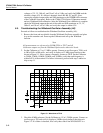
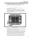
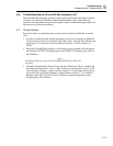
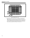
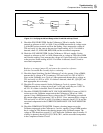
3. Check the Complimentary Drive Circuit. Set the Calibrator to 200 µA, standby. Set
the external ac reference to 7.0V at 1 kHz. Connect an oscilloscope to pin 11 of K2
and verify that it displays a signal similar to Figure 5-6. Connect the oscilloscope to
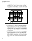
pin 6 of K2 and verify that it displays a signal similar to Figure 5-7. If a failure is
detected, check Q2, Q3, Q18, Q19, K2, and their associated components in the
Complimentary Drive Circuit.