


Theory of Operation
Analog Section Detailed Circuit Description
2
2-61
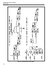
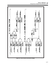
The internal cal zero amplifier is outlined in a broken line rectangle on sheet 1 of the
schematic. Its functional parts are U20-U21, R38-44, R46-47, Q6-7, Q11, and Z2. When
Q7 is on, the input of the zero amplifier is connected to 0V for a reference point. When
Q6 is on, the gain of the zero amplifier is 130. Op amp U21 and its associated resistors
form a current-cancellation circuit. It senses the output of the zero amplifier and creates
a current equal in magnitude but opposite in polarity to the current through the gain
resistors (Z2), resulting in zero current in the precision common (RCOM).
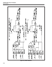
2-99. Switch Matrix 5725A Amplifier Interface
The Switch Matrix also provides switching between the calibrator and the 5725
Amplifier. The ac and dc input signals necessary to operate the 5725A are connected by
relay K22. Relay K23 connects B SNS LO to either OSC SENSE LO or R COM via
relay K14.
2-100. DAC Assembly (A11)
The DAC (digital-to-analog converter) is the basic building block of the calibrator. Other
assemblies create ac and dc voltages and currents with its precision dc voltage. The DAC
contains five assemblies:
• DAC Main Board (A11)
• DAC Filter SIP (A11A1)
• DAC Buffered Reference SIP (A11A2)
• Reference Hybrid (HR5)
• DC Amplifier Hybrid (HR6).
The DAC assembly serves two main functions:
• To provide a highly repeatable stable dc voltage
• To support calibration of the calibrator
The DAC’s adc circuit is used to accomplish calibration. It is made up of an analog to
digital converter (adc) and the adc amplifier. Together, these are used to completely
characterize the calibrator, using only one external voltage source and two external
resistor standards.
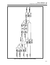
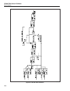
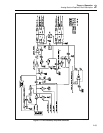
2-101. Basic DAC Theory of Operation.
Figure 2-17 is a simplified schematic of the DAC assembly. The DAC uses a pulse-
width-modulated scheme to produce a precision dc voltage of 0V to 22V with positive
and negative polarity. The DAC contains:
• A 13V temperature-controlled reference hybrid (HR5)
• Duty-cycle control circuitry
• A five-pole active filter (A11A1 assembly)
• An output stage
• Digital control circuitry
• These basic subcircuits work together for a stable and linear dc voltage.
The DAC assembly also contains:
• A sense-cancellation circuit
• Linearity control circuits
• Negative offset circuit
• An output switching circuit
The two inputs of the five-pole filter are two precision square waves with different fixed
amplitudes and independently variable duty cycles controlled by software. The filter’s