


5700A/5720A Series II Calibrator
Service Manual
5-44
frequency counter to TP3 and adjust the external dc reference until the frequency
counter reads 64 MHz ±0.1%. Using the frequency counter, measure the frequency
at TP4 and verify it reads 32 MHz ±0.1%. If a failure is detected, check U4 and
associated components. Next, measure the frequency at pins 15, 13, 4, and 2 of U5
and verify that pin 15 measures 16 MHz ±0.1%, pin 13 measures 8 MHz ±0.1%, pin
4 measures 4 MHz ±0.1%, and pin 2 measures 2 MHz ±0.1%. If a failure is detected,
check U5 and associated components.
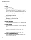
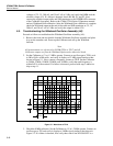
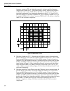
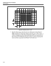
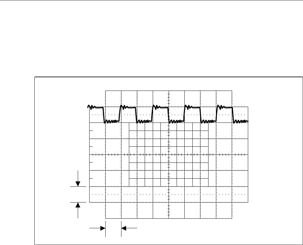
1 V
10 ms
F5-3.EPS
Figure 5-3. Waveform at TP15
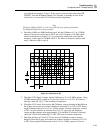
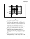
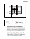
8. Check the Synthesizer IC U1. Power down the Calibrator, remove shorting header
E6 from the J6 pins, and connect an external variable dc reference (2 to 13V) to TP2.
Power up the Calibrator and set it for 1V at 6 MHz, operate. Connect a frequency
counter to TP15 and adjust the external dc reference until the counter reads less than
6 MHz (~5.8MHz). Connect an oscilloscope to pin 15 of U1 and verify it displays a
signal similar to Figure 5-4. Next, adjust the external dc reference until the counter
reads more than 6 MHz (~6.2 MHz).Connect an oscilloscope to pin 14 of U1 and
verify it displays a signal similar to Figure 5-4. If a failure is detected, check U1 and
associated components.
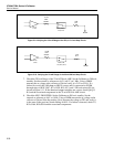
9. Check the Amplifier Circuit. Power down the Calibrator, remove shorting header E6
from the J6 pins, and connect an external variable dc reference (2 to 13V) to TP2.
Power up the Calibrator and set it for 1V at 6 MHz, operate. Connect a frequency
counter to TP15 and adjust the external dc reference until the counter reads less than
6 MHz (~5.8 MHz). Connect an oscilloscope to pin 6 of U2 and verify it displays a
positive dc voltage. Next, adjust the external dc reference until the counter read more
than 6 MHz (~6.2 MHz) and verify the oscilloscope connected to pin 6 of U2
displays a negative dc voltage. If a failure is detected, check U2 and associated
components.