5700A/5720A Series II
Service Manual
iv
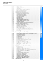
2-113. ADC Amplifier............................................................................ 2-69
2-114. ADC Input Selection.................................................................... 2-69
2-115. ADC Circuit................................................................................. 2-70
2-116. How the DAC is Used in Calibration .......................................... 2-72
2-117. DAC Assembly Calibration......................................................... 2-72
2-118. Oscillator Section Overview............................................................ 2-73
2-119. Oscillator Control Assembly (A12)................................................. 2-73
2-120. Oscillator Control Digital Control............................................... 2-74
2-121. Oscillator Input Switching........................................................... 2-74
2-122. Sense Current Cancellation ......................................................... 2-74
2-123. Averaging Converter.................................................................... 2-75
2-124. Error Integrator............................................................................ 2-75
2-125. Three-Pole Filter.......................................................................... 2-75
2-126. Analog Amplitude Control Loop................................................. 2-75
2-127. AC/DC Thermal Transfer Circuit................................................ 2-77
2-128. Oscillator Calibration .................................................................. 2-79
2-129. AC/DC Frequency Response Characterization ........................... 2-80
2-130. Oscillator Output Assembly (A13) .................................................. 2-80
2-131. Oscillator Output Digital Control................................................ 2-82
2-132. Quadrature RC Oscillator............................................................ 2-82
2-133. Oscillator Amplitude Control...................................................... 2-83
2-134. Phase−locked Loop...................................................................... 2-83
2-135. 2.2V and 22V Range Output Amplifier....................................... 2-84
2-136. Oscillator Wideband Smd Assembly (A13A1) ........................... 2-84
2-137. Output Stage ................................................................................ 2-85
2-138. Phase Shifter................................................................................ 2-85
2-139. Power Amplifier Assembly (A16) ................................................... 2-85
2-140. Power Amplifier Digital Control Sip Assembly (A16A1) .......... 2-86
2-141. PA Common Circuitry................................................................. 2-87
2-142. +PA and -PA Supplies................................................................. 2-87
2-143. PA Input Stage............................................................................. 2-87
2-144. PA Mid Stage............................................................................... 2-88
2-145. PA Output Stage .......................................................................... 2-88
2-146. PA Sense Current Cancellation Circuitry.................................... 2-89
2-147. PA in Standby.............................................................................. 2-89
2-148. PA Operation: 220V DC Range .................................................. 2-89
2-149. PA Operation: 220V AC Range .................................................. 2-91
2-150. High Voltage Assembly Support Mode....................................... 2-91
2-153. 220V DC Internal Calibration Network ...................................... 2-92
2-154. PA Calibration ............................................................................. 2-92
2-155. High Voltage Assemblies (A14 and A15) ....................................... 2-96
2-156. 1100V AC Range......................................................................... 2-96
2-157. 1100V DC Range......................................................................... 2-98
2-158. HVDC Power Supply Filter Circuit............................................. 2-98
2-159. HV DC Output Series Pass and Current Limit Circuit................ 2-98
2-160. DC HV Amplifier/AC Sense Buffer............................................ 2-100
2-161. 2.2A Range .................................................................................. 2-100
2-162. 2.2A Power Supply Filter Circuit................................................ 2-102
2-163. High Voltage Digital Control ...................................................... 2-103
2-164. High Voltage Calibration............................................................. 2-104
2-165. Calibration of the AC Function ................................................... 2-104
2-166. Calibration of the Current Function. ........................................... 2-106
2-167. High Voltage Magnitude Control................................................ 2-106
2-168. Ohms Overview ............................................................................... 2-108


