4−14 Installation and Maintenance Volume
Octel 200/300 S.4.1 PB60019−01
4.3 TERMINAL COMMUNICATIONS
You can establish communication with the message server by connecting a local terminal, by calling in
through an internal or external modem, or by using the Telnet feature. The Telnet and internal modem
accesses are mutually exclusive. However, the direct connection can exist in “listen only” mode when
either remote access path is used. The direct terminal must be at the @ prompt to allow any form of
remote access.
The Octel 200/300 works with any ASCII send/receive serial terminal/teleprinter that meets RS-232C
specifications.
Regardless of whether the connection is through the internal modem or through Telnet, the message
server automatically logs off if there is no activity within the time specified in System Parameter 286 —
TERMINAL INACTIVITY LOGOUT TIMER (MINUTES). The default is 15 minutes. Refer to the
Configuration volume, SYSTEM PARAMETER Table chapter.
Inactivity logout does not occur when the system administrator is in the midst of a non-interactive
command, such as running a List Trace or running a report. This could take several minutes to complete.
Terminal Installation
The maximum recommended distance between the terminal and the Octel 200/300 is no more than 50
feet, which is the length of a standard RS-232C cable.
The Octel 200/300 uses even parity, 7 data bits, 1 stop bit, and XON/XOFF protocol.
Connect the terminal to the message server terminal port. Two functionally equivalent connections allow
for convenient access:
- The front connection (SP1) for temporary access
- The rear connection (J1) for permanent access
The terminal should have the capability of making a hard copy printout. You can use a PC with terminal
emulation software to achieve information and sessions to a file.
Cable Connections Between the RS-232C Terminal and the
Octel 200/300
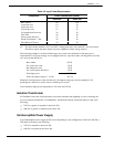
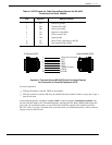
The system terminal port (SP1 or J1) uses standard 25-pin (DB25) RS-232C connectors (female), with the
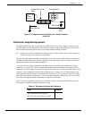
DCE pinouts listed in Table 4-4. Figure 4-6 is a diagram of these pinouts. J2 is used when the server is
integrated to a PBX/Centrex using an RS232 link. On the Octel 300, J3 and J4 are reserved for future
use. All ports are configured to use the same pinouts as listed in Table 4−4 and shown in Figure 4−6.


