Hardware Replacement 9-39
Octel 200/300 S.4.1PB60019−01
Tools Required
Make sure the following tools (or their equivalent) are on hand before continuing:
- Large flat-blade screw driver (for loosening and tightening the captive fasteners on the front of the
power supply assembly.
- Regular blunt-tip Phillips-head screw driver (required only for the Octel 300 procedure; used to
remove and replace screws that hold the Top Rear Panel Assembly and Power Filter Assembly).
. The procedures for the Octel 200 and Octel 300 are different. Be sure to use the correct
procedure.
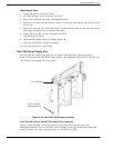
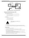
Octel 200 PSU Replacement Procedures
Use this procedure to replace an existing Octel 200 PSU:
- 120 VAC PSU/Floppy Assembly (740−6504−001) or
- 230 VAC PSU/Floppy Assembly (740−6505−001)
with:
- Octel 200 100−240 VAC Auto-ranging PSU/Floppy Assembly (740−6640−000).
1. Take antistatic precautions (wear an antistatic wrist strap and connect the strap cable to an unpainted
ground point in the cabinet chassis).
2. Power down the Octel 200 (make sure the power switch is positioned so that the bottom of the
rocker, marked with a 0, is pressed in).
3. Disconnect the floppy drive ribbon cable from the CPU Card.
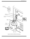
4. Unscrew and remove the original 120 VAC or 230 VAC PSU/Floppy Assembly and store
appropriately. The PSU/Floppy Assembly is heavy. While removing the unit with one hand, use the
other hand to provide support from underneath.
5. Pick up the new 100−240 VAC PSU/Floppy Assembly with one hand on the handle and the other
hand under the unit to support its weight. Support the PSU by holding the sheet metal slider. Do not
touch any power supply electrical components or wiring.
6. Line up the edges of the PSU sheet metal with the card guides marked A10, and slide the PSU
halfway into the cabinet. Remove your supporting hand from the bottom of the sheet metal plate.
7. Confirm that the power switch on the front of the new PSU is in the OFF (0) position.
8. Gently, but firmly, continue to slide the PSU into the cabinet by pushing on the handle until the
connectors on the back of the PSU have mated with the connectors on the motherboard. This is
accomplished when the flange on the front sheet metal of the PSU reaches or very nearly reaches the
sheet metal of the cabinet.
Caution!
Do NOT slam the PSU into the cabinet. Doing so
could damage the PSU.


