DTIC 10-5
Octel 200/300 S.4.1PB60019−01
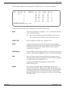
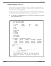
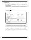
The following example shows only eight ports. The DTIC can have up to 30 ports configured.
SLOT CARD TYPE PORT EXTENSION # COS MODE OUTCALL TEST SYS
−−−− −−−−−−−−− −−−− −−−−−−−−−−− −−− −−−− −−−−−−− −−−− −−−
4 DTC17−E11 254 AX NO NO 7
2 254 AX NO NO 8
3 254 AX NO NO 9
4 254 AX NO NO 10
5 254 AX NO NO 11
6 254 AX NO NO 12
7 254 AX NO NO 13
8 254 AX NO NO 14
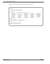
LSPTAB table: QSIG
SECONDARY SYNC RECEIVER OF CLOCK
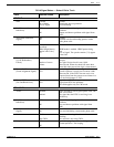
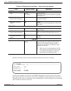
The following describes the valid or invalid entries for the SLOTS Table fields:
Enter the slot number to be configured — slots 1−6 for the Octel 200 and
slots 1−7 for the Octel 300.
. Because the grounding strip used for the DTIC is only for seven
slots, in effect the slots available for the Octel 300 are slots 1−7.
Enter the number for a DTIC card — 23−DTC17−E1.
Configure the ports in consecutive order. Specifies the port (channel)
number on a card. DTIC cards have 30 channels each. If two DTIC cards
are installed in slots 1 and 2, the channel numbers on the card in the
second slot start with port 31.
Enter the PBX extension number connected to each message server port. A
mailbox extension number cannot be the same as a port extension number.
Enter the COS for each port on the card. Directs the message server to
other system tables for the days and times to activate features and where to
get further instructions for handling the call.
Assign port/trunk COS in descending order, starting with the
highest-numbered COS.
Enter the Answering Mode. Must be either Primary Answer (AX),
Secondary Answer (CX), or Message Center (MX). Determines how the
message server handles the call when that port answers. For further details
on answering modes, refer to the Product Description volume, General
Description chapter, and to the Configuration volume, Slots Table chapter,
Line Cards section.
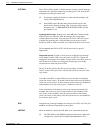
SLOT
CARD TYPE
PORT
EXTENSION #
COS
MODE


