4−28 Installation and Maintenance Volume
Octel 200/300 S.4.1 PB60019−01
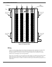
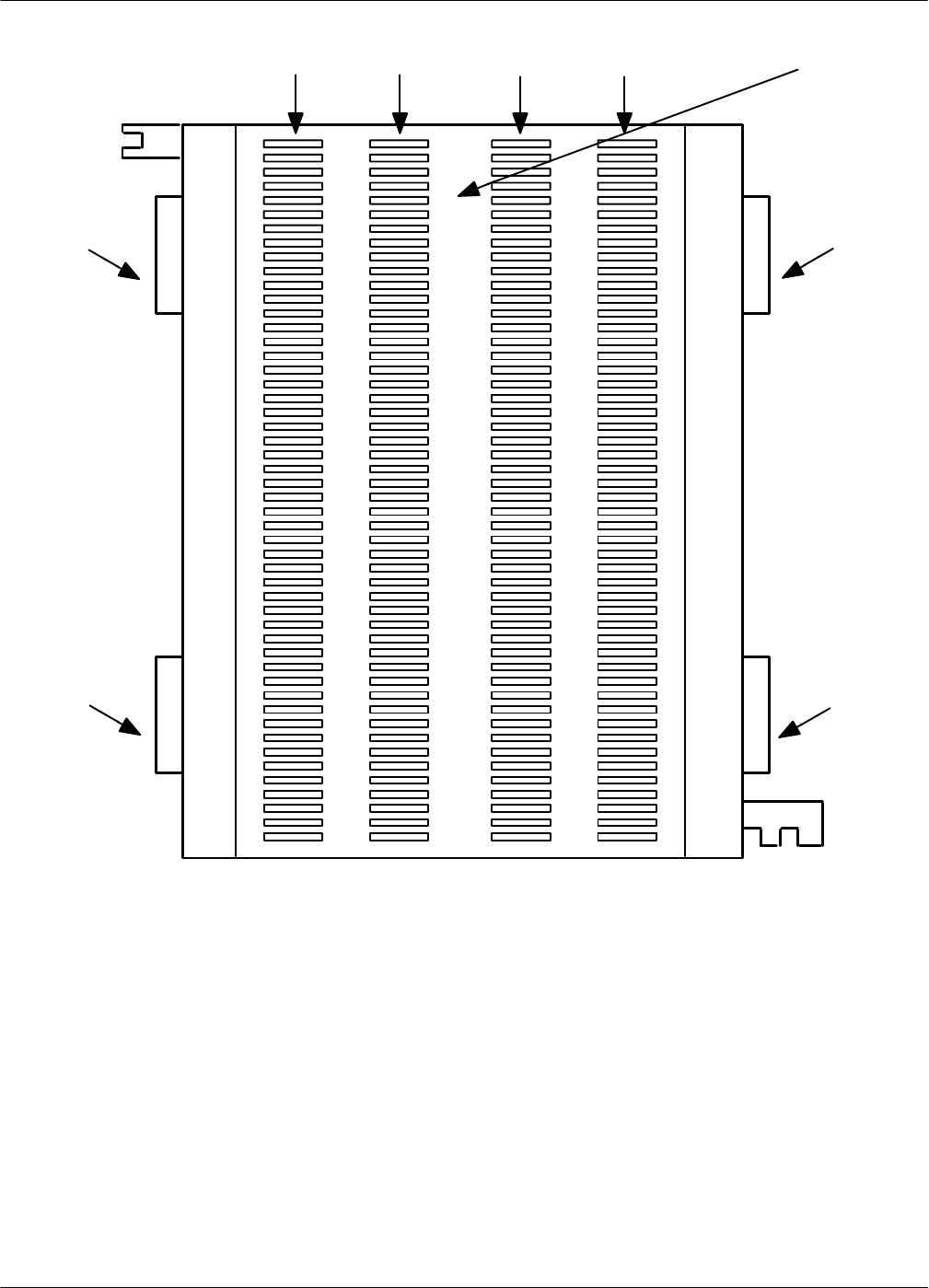
Figure 4-9 Connector Block
A B
C DColumn =
1
2
3
4
5
6
7
8
9
10
11
12
13
14
15
16
17
18
19
20
21
22
23
24
25
Pair
Number
Jack 3 (C)
to slot 3
Jack 4 (D)
to slot 4
Jack 1 (A)
Jack 2 (B)
to slot 2
To p
to slot 1
Wiring
In most cases, the existing wiring is not consistent in its placement of the connections. To isolate faults
quickly, it is recommended that the slots be connected in numerical order, allowing for known or
anticipated expansion. Also make sure that the slot and port numbers can be translated to extension
numbers that are meaningful to the servicing technician.
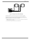
Figure 4-10 is an example of a 16-port message server that requires one connector block and four 25-pair
cables. From the rear of the cabinet, connect the first 25-pair cable from P1 to jack position 1 of the
66M4-4W connector block, or column A; connect the second 25-pair cable from P2 to jack position 2, or
column B; etc.


