Hardware Replacement 9-7
Octel 200/300 S.4.1PB60019−01
Octel 300 Diagrams
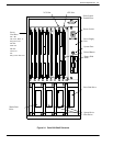
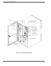
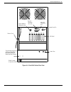
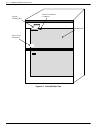
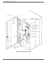
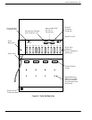
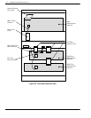
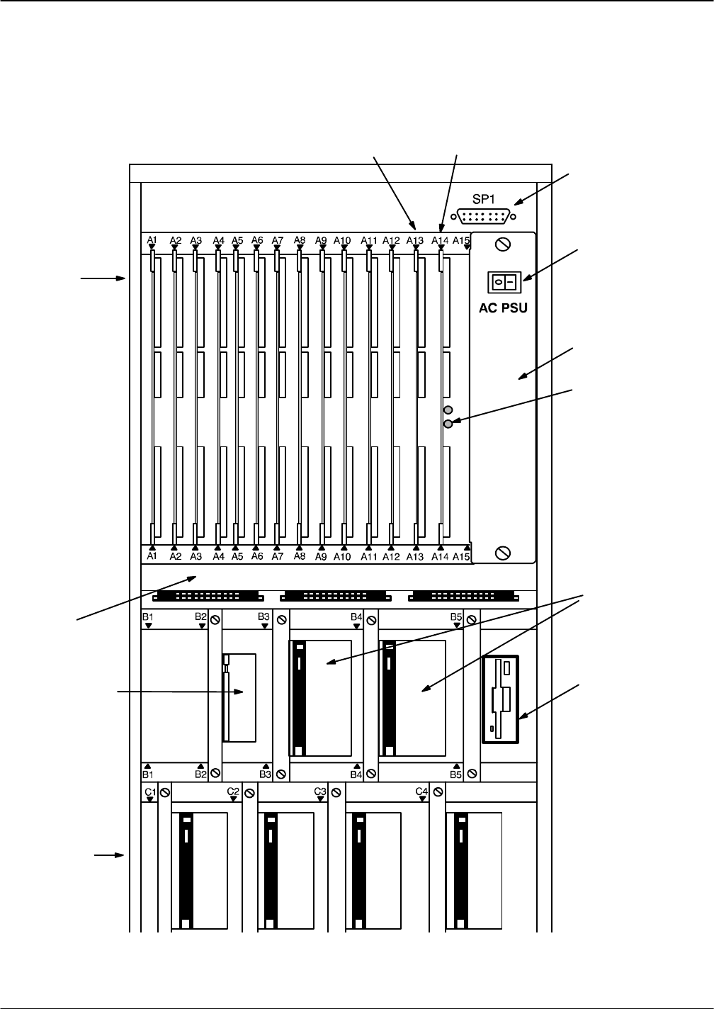
Use the following Octel 300 diagrams when performing preventive maintenance or replacing
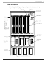
components. Figure 9-5 through Figure 9-8 illustrate the front, rear, and inside views.
Front System
Terminal Port
Power Supply
Unit
Floppy Disk
Drive
Power Switch
Works Disk
Drive
Four Voice
Disk Drives
System/Voice
Disk Drives
Fan Tray
VCU Slot
CPU Slot
Twelve
Card Slots
A1 − A11:
LIC, TLC, DAC
,
or Integration
card
A1−A12
FAX card
A10−A12
LAN card
A12:
Entryworks ACP,
LIC, FAX, TLC
,
Integration card
Reload Button
Figure 9-5 Octel 300 Shelf Structure


