9-18 Installation and Maintenance Volume
Octel 200/300 S.4.1 PB60019−01
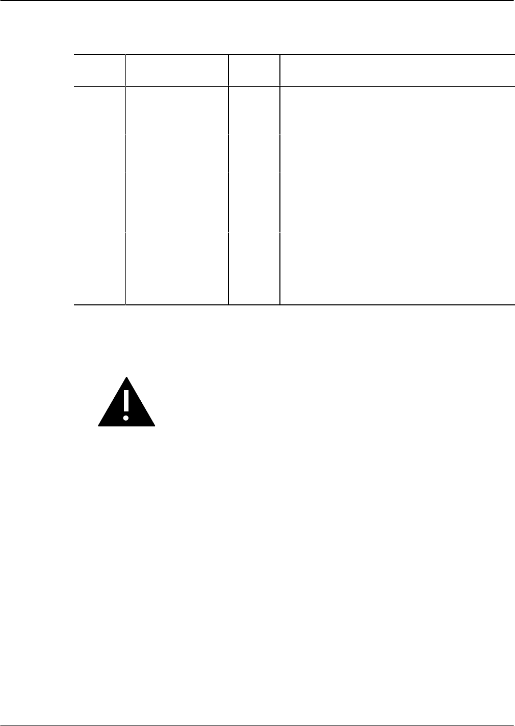
Once the LAN card is installed, the LEDs on the LAN card are activated, as follows:
LED
Number
LED Description LED
Color
LED Activity
1 Standard use Red Lit when the LAN card is installed. Goes off when the
card has been initialized and is ready for operation.
2 Standard use Green Lit when self-test diagnostics are complete.
3 Development Yellow Used only for development.
4 Good link indicator Yellow Lit when the adapter and wiring to a hub are correct.
5 Rx polarity reversed Yellow Lit if the pair being received by the Ethernet
controller needs to be reversed. Check the wiring.
6 Receive activity
Indicator
Yellow Lit when the Ethernet controller sees activity on the
receive pair.
7 Transmit activity
indicator
Yellow Lit when the Ethernet controller sees activity on the
transmit pair.
8 Collision Indicator Yellow Lit when a collision occurs. Collisions occur normally
in Ethernet/802.3 networks, because it is part of the
low layer protocol.
DTIC Replacement
The Digital Trunk Interface Cards (DTIC) installed in Shelf A are “hot pluggable.” That means the
system does not need to be powered down to remove or install the cards.
Caution!
No more than one card at a time may be removed or
installed with power ON.
Installing a DTIC Card for a New Installation
These procedures are for installing a DTIC card in a new installation. If you are replacing a DTIC card in
an existing installation, use the procedures in the next section, Replacing a DTIC Card in an Existing
Installation.
. Configure the SLOTS Table for the DTIC card before installing the card.
1. Put on an antistatic wrist strap and connect it to an unpainted portion of the cabinet.
Install the DTIC−E1 kit as follows:
2. On the I/O panel on the back of the server, remove the two jack screws and washers securing the
connector marked as follows:
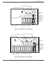
- J2 (for the Octel 200). Refer to Figure 9-11.
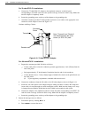
- J4 (for the Octel 300). Refer to Figure 9-12.
3. Using two new jack screws provided with the kit and washers just removed, attach the grounding
strip where shown in Figure 9-11 for the Octel 200 or Figure 9-12 for the Octel 300.
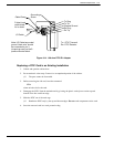
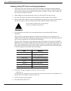
4. Install the DTIC adapter by following the steps below for either a 75-ohm or 120−ohm DTIC−E1
adapter, then proceed to Step 5.


