INSTALL 1-13
Octel 200/300 S.4.1PB60019−01
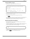
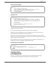
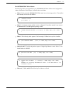
Direct Access Card (DAC)
SLOT 2:7
Enter information for each PORT.
Enter as: EXTENSION NUMBER connected to each port (1−8 digits),
CLASS−OF−SERVICE (0−254), SIGNALLING (DTMF, Rotary),
TRUNK TYPE (Wink, Immed, Delay, Loop, Ground).
1 :333,254,DTMF,DELAY
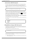
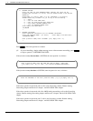
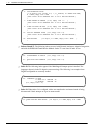
Integration Card
SLOT 4 :5
Enter information for each PORT.
Enter as: EXTENSION NUMBER connected to each port (1−8 digits),
CLASS−OF−SERVICE (0−254), ANSWER MODE (AX, CX, MX), USE PORT FOR
MESSAGE WAITING AND NETWORK OUTCALLING (Y/N), TEST CHANNEL (Y/N)
1 :334,250,AX,N,N
2:
Configure Integration (1−4=Msg Waiting Link):1
Enter empty line when done.
INS:
Integration cards must be the same.
For the Octel 200, Integration cards can be installed in Slots A1 through A6.
For the Octel 300, most integration cards can be configured in any slot not used for line cards.
ATTIC integration cards and SIC8 cards cannot go in slot 12.
Except for the AT&T System 75/Definity G1, and the G3 ATTIC integrations, each port can be
allocated to only one integration unit. Refer to the Integration volume for additional details about the
specific integration you are configuring.
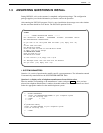
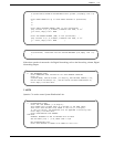
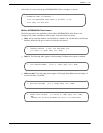
The fax application processor card can be installed in any unoccupied slot. The following is an
example of the dialog for configuring a fax application processor.
Fax Application Processor Card
.SLOT 8:17
Enter information for each PORT.
Enter as: CLASS-OF-SERVICE ( 0−254 ), TEST CHANNEL (Y/N).
1:126,N
2:126,N
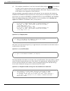
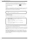
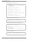
4. NETWORK ROUTES
5. NETWORK LOCATIONS
6. NET NUMBERING PLAN
Questions 4, 5, and 6 pertain to collocated message servers and multilocation networking.
For information about configuring networking, refer to the Networking volume.


