10-4 Installation and Maintenance Volume
Octel 200/300 S.4.1 PB60019−01
- System Parameter 175 — PORT NUMBER FOR CALL RECORDS TO FIRST PORT.
These settings are site specific and depend on the numbering of PBX extensions. The following is an
example of settings for the four parts of this parameter:
- Number of digits in the extension number fields to 5
- Number of digits in the port number field to 3
- Fill character to 0 (zero)
- Port number used in call records to 1
- System Parameter 198 — PCM ENCODING FOR THE SYSTEM.
Set to 1, for A-law, or 0 for mu-law.
Voice data is encoded, in the E1 environment, into 8 bit numbers (called octets) that are sent 8000
times per second for each port. This process of sampling and encoding analog voice to these octets is
called Pulse Code Modulation (PCM). PCM uses two standard algorithms for conversion: A-law,
which is used primarily in Europe, and mu-law, which is used in North America. If DTIC voice
quality sounds consistently bad but still recognizable, the DTIC could be operating with the wrong
PCM law. To correct this low voice quality, change the PCM law and restart the message server.
Important: If a DTIC card is configured for A-law, 4- or 8-port line cards cannot be used:
- To receive fax calls
- For modem connection using the
# # # 5
command
Class of Service
A COS must be configured for each of the 30 DTIC ports. Assign attributes as required. Refer to the
Configuration volume, COS chapter.
SLOTS Table
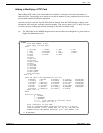
The slot where a DTIC is to be installed must be added to the SLOTS Table. Adding a slot for a DTIC is
similar to adding a slot for other line cards. However, there are some questions pertaining specifically to
the DTIC.
Slots can be skipped, as for any line cards. However, the grounding strip is for only the first seven slots.
With Capacity on Demand, the number of ports for the DTIC are purchased as required.
After the slot is configured, the system must be restarted for the DTIC to become operational.
Configuring Slots for the DTIC
The DTIC card is physically connected to a PBX extension (a single line) via two 75-ohm coax cables to
support 30 ports. The PBX directs calls to the message server for answering.
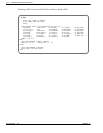
The SLOTS Table contains information about each port on the DTIC card.
Each port connected to a PBX extension can be configured to handle calls differently. For non-integrated
systems, the port extensions must be set up in one or more hunt groups in the PBX. Each hunt group can
be configured to handle calls differently.


