


6-3SectionUsing No-protocol Communications
101
6-3 Connections
The connection examples in this section show only the basic connection dia-
grams. We recommend that appropriate noise countermeasures be taken in ac-
tual applications, including the use of shielded twisted-pair cables. Refer to 2-3
Wiring for actual wiring methods.
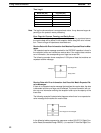
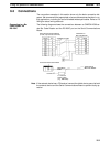
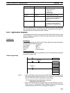
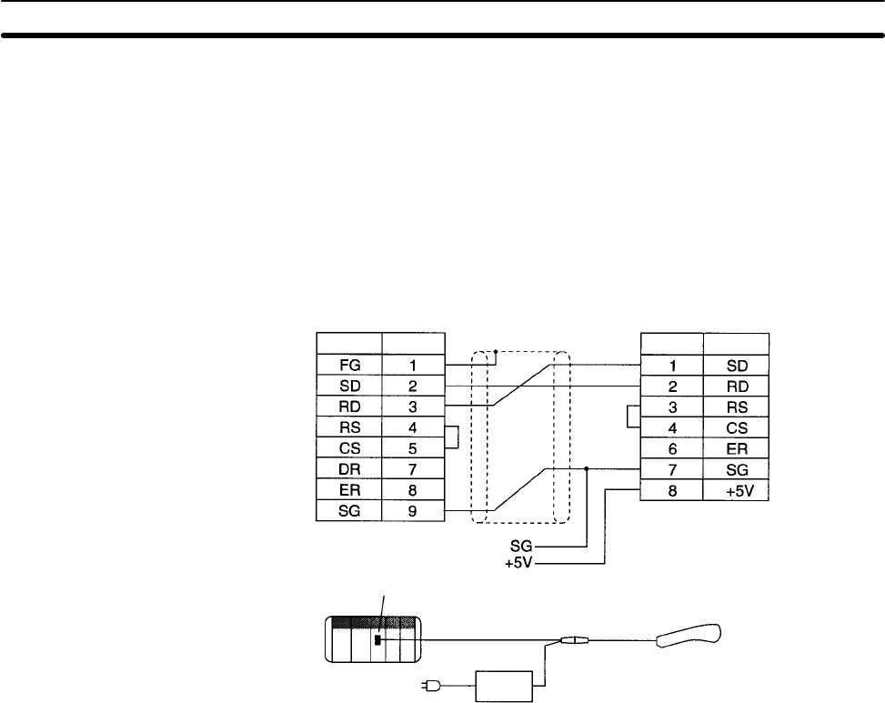
The following diagram shows the connections between an OMRON V500-se-
ries Bar Code Reader and the RS-232C port on the Serial Communications
Board.
Serial Communications Board
(D-sub, 9-pin female connector)
Signal Pin SignalPin
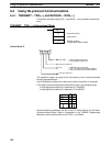
V520-RH21-6
Bar Code Reader
V509-W012 Cable
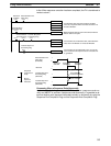
Serial Communications Board
V509-W012
Cable
5-V external
power supply
(e.g., 82S-0305)
100 VAC
V520-RH21-6
Bar Code Reader
Note If the external device has a FG terminal, connect the shield wire to ground at both
the external device and the Serial Communications Board to prevent faulty op-
eration.
Connecting to a Bar
Code Reader via
RS-232C