


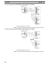
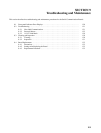
9-2SectionBoard Replacement
121
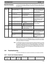
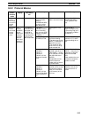
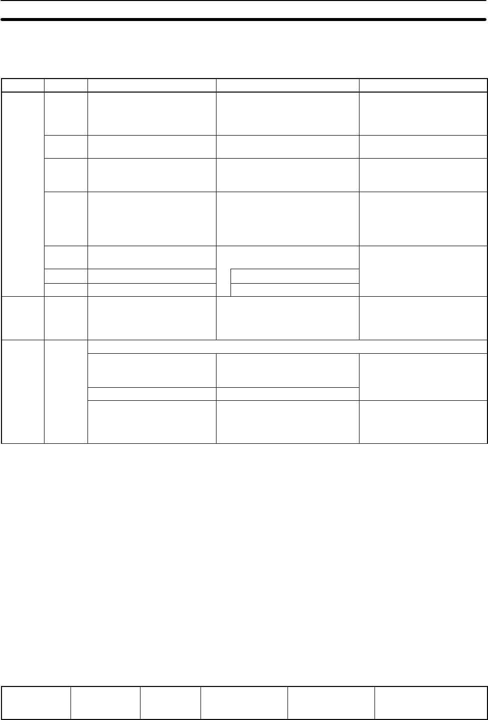
For Serial Communications Boards, refer to the following error flags. When an
error occurs, the corresponding flag is turned ON. All of these flags represent
non-fatal errors.
Word Bit Name Probable cause Possible remedy
IR 200
00 Serial Communications Board
Hardware Error Flag
The Board has failed. Secure the Board firmly in the
slot or try it in a different CPU
Unit. If the problem persists,
replace the Board.
01 Port Identification Error Flag
(hardware error)
There is a problem with the
communications port.
Replace the Board.
02 Protocol Data Error Flag A checksum error was found in
the protocol data.
Retransfer the protocol data.
If the problem persists,
replace the Board.
12/11 Protocol Macro Execution
Error Flag (Port 1/2)
An error occurred when the
PMCR instruction was executed.
Take countermeasures
according to the error codes
stored in bits 08 to 11 (port 1)
or bits 12 to 15 (port 2) in
word 204.
15 PC Setup Error Flag There is an error in the settings in
the PC Setup.
Check the settings for the
Board in the PC Setup and
14 Port 1 PC Setup Error Flag
Error in settings for port12.
restart the Board.
13 Port 2 PC Setup Error Flag Error in settings for port 2.
SR 254 15 Slot 1 Inner Board Error Flag Turns ON when an error occurs
in the slot 1 Inner Board. The
error code for slot 1 is stored in
AR 0400 to AR 0407.
See remedies for AR 04.
AR 04 00 to 07
Slot 1 Inner Board Error Code
01: Hardware error The Board has failed (watchdog
timer error). IR 20000 will also be
ON.
Secure the Board firmly in the
slot or try it in a different CPU
Unit. If the problem persists,
02: Hardware error The Board has failed.
replace the Board.
10: Serial Communications
Board error
Refer to the errors in IR 200. See remedies for IR 20000,
IR 20001, IR 20002, IR
20011, IR20012, and
IR 20015.
When a fatal error occurs, the ERR/ALM indicator on the CPU Unit will light.
When a non-fatal error occurs, the ERR/ALM indicator on the CPU Unit will flash.
Refer to the indicator error displays.
Note The ERR/ALM indicator will continue to flash even after the cause of a non-fatal
error has been removed for the Serial Communications Board. The indicator can
be stopped by clearing the error from a Programming Console or other Program-
ming Device. Press the FUN Key and then the MONITOR Key from the Pro-
gramming Console. Refer to the CX-Programmer Operation Manual for the CX-
Programmer procedure.
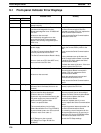
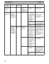
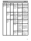
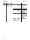
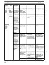
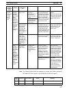
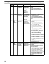
9-2 Troubleshooting
This section describes how to resolve transmission and reception problems.
9-2-1 Host Link Communications
Serial com-
munications
mode
Indicator
status
Status
information,
etc.
I/O memory Cause Remedy
Serial Communications
Board Error Information