


9-4SectionBoard Replacement
132
9-4 Board Replacement
A malfunction of the Serial Communications Board may affect the operation of
remote communications devices, so be sure to perform repairs or replace the
faulty Board promptly. Make sure a spare Serial Communications Board is avail-
able to replace a faulty one, so that functionality can be restored without delay.
9-4-1 Precautions
Observe the following precautions when replacing the Serial Communications
Board.
• Always turn OFF the power to the PC before replacing the Serial Communica-
tions Board.
• Be sure to check that the Serial Communications Board replacing the faulty
one is not defective.
• If the defective Serial Communications Board is to be dispatched to the
manufacturer for repair, be sure to include documentation stating the nature of
the fault in as much detail as possible, and send to your nearest OMRON
branch or sales office, listed at the back of this manual.
If the contacts are defective, clean the contacts with a clean all-cotton cloth
moistened with industrial-strength alcohol. Remove any cloth particles before
mounting the Serial Communications Board.
Note Turn OFF the power to all serial external devices when replacing the Serial Com-
munications Board to prevent malfunctions.
9-4-2 Settings after Replacing the Board
After replacing the Serial Communications Board, make sure that wiring and set-
tings, such as hardware switch settings, the settings for the Serial Communica-
tions Board in the PC Setup, and protocol macro data are the same as the Serial
Communications Board that was replaced.
Note 1. If the CPU Unit is to be replaced, transfer to the replacement CPU Unit the
contents of the Holding Areas and DM Area required for operation before
starting operation. If the relationship between the DM Area and Holding
Area and the program is not maintained, unexpected malfunctions may re-
sult.
2. The PC Setup of the Serial Communications Board is saved in the DM Area
of the CPU Unit. If the CPU Unit is to be replaced, either transfer the PC Set-
up data to the CX-Programmer or CX-Protocol before replacing the CPU
Unit or reset the PC Setup.
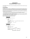
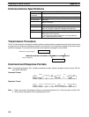
9-4-3 Replacement Procedure
Standard System Protocols, Host Link Communications, No-protocol Communications, 1:1 Data
Links, or NT Links
1, 2, 3... 1. Turn OFF the power to the PC to which the Serial Communications Board to
be replaced is mounted, and to all serially connected external devices.
2. Disconnect the communications cables connected to the Serial Commu-
nications Board to be replaced, and also remove the Serial Communica-
tions Board.
3. Set the hardware switches of the replacement Board to the same settings of
the Serial Communications Board being replaced before mounting, as fol-
lows:
• Terminating resistance switch (TERM)
• The 2/4-wire switch (WIRE)