Appendix H
ES100j Digital Controller Protocol
246
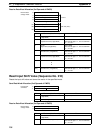
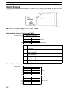
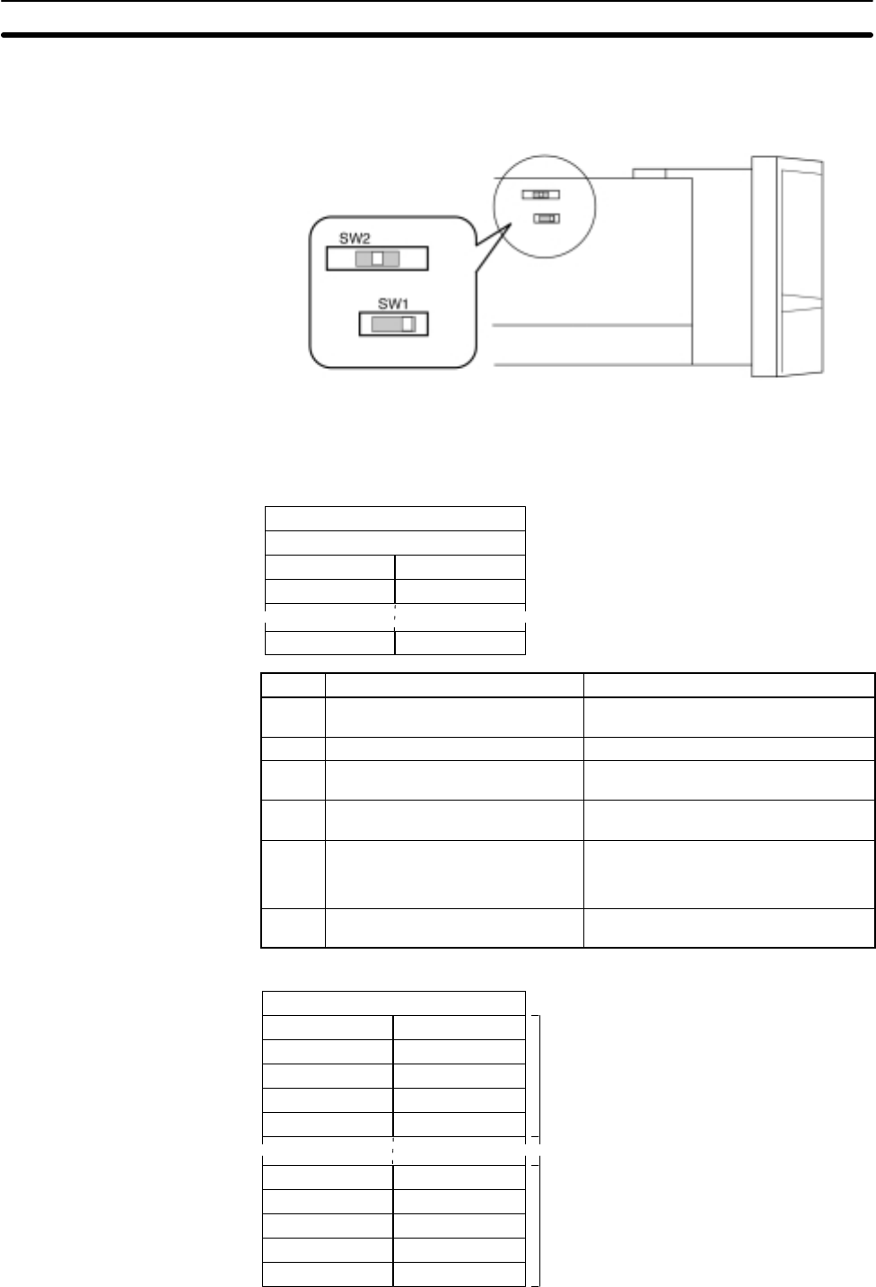
Switch Settings
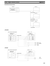
There are two switches located on the board on the left of the Unit. Set SW1 to the interface: RS-422A or RS-485.
Set SW2 to the center on all terminating Units and to the same setting as SW1 on all other Units.
422← S →485
422← S →485
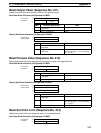
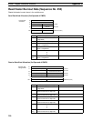
Read Event Data (Sequence No. 250)
Reads events 1 to 10 in the variable area.
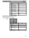
Send Data Word Allocation (2nd Operand of PMCR)
(Undefined)
Unit No.
First word of send
data
Number of send data words+0
+1
+2
+3
+26
(Undefined)
Unit No.
Number of units
(Undefined)
Unit No.
~ ~
25th unit (max.)
2nd unit
1st unit
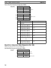
Offset Contents (data format) Data
+0 Number of send data words
(4 digits BCD)
Number of units + 2
+1 Number of units (4 digits BCD) 0001 to 0025
+2 1st unit
Unit No. (2 digits BCD)
00 to 31
+3 2nd unit
Unit No. (2 digits BCD)
00 to 31
D
D
D
+26
(max.)
25th unit
Unit No. (2 digits BCD)
00 to 31
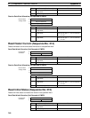
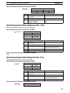
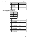
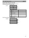
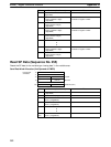
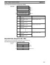
Receive Data Word Allocation (3rd Operand of PMCR)
Event 1
Event 9
Event 2
Receive data
storage words
Number of receive data words+0
+1
+2
+3
+4
+5
+121
+122
+123
+124
+125
Event 1
~ ~
1st unit
25th unit (max.)
Event 2
Event 3 Event 4
Event 5 Event 6
Event 7 Event 8
Event 10
Event 3 Event 4
Event 5 Event 6
Event 7 Event 8
Event 9 Event 10


