!
2-1SectionWiring
13
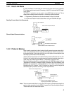
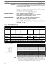
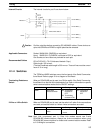
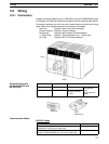
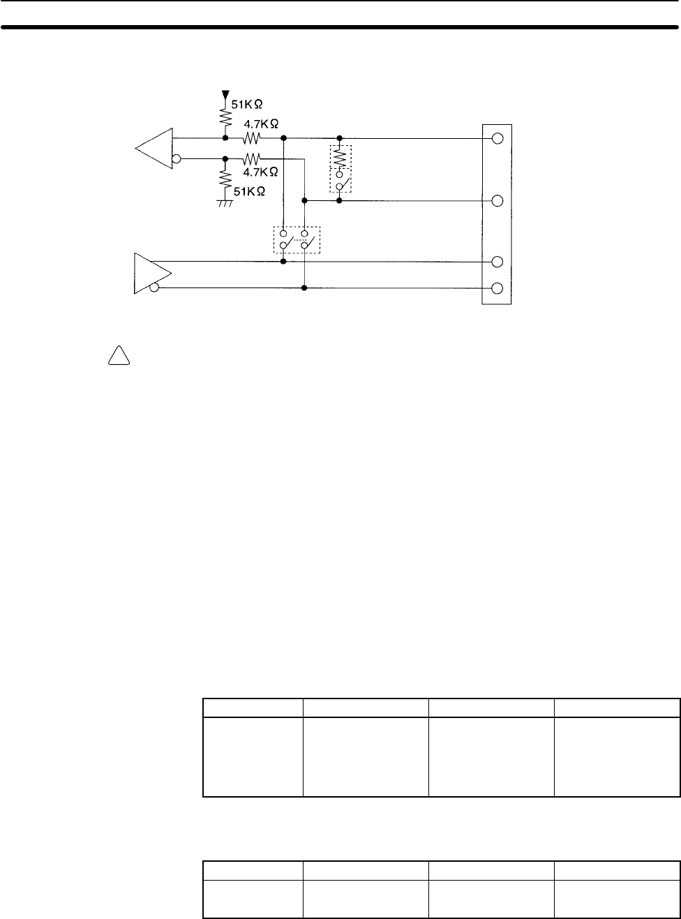
The internal circuits for port 2 are shown below.
Receiver
Driver
Terminating resistance: 200 Ω
Terminating resistance switch
2-wire/4-wire switch
Pin 8: RDB (+)
Pin 6: RDA (–)
Pin 2: SDB (+)
Pin 1: SDA (–)
Caution Confirm polarities before connecting RS-422A/485 cables. Some devices re-
quire that SDA/B and RDA/B or signal polarities be reversed.
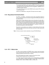
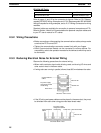
Socket: XM2A-0901 (OMRON) or equivalent
Hood: XM2S-0911-E (OMRON, conforms to ESD) or equivalent
One Socket and one Hood are provided for each port.
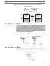
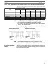
CO-HC-ESV-3P 7/0.2 (Hirakawa Hewtech Corp.)
Cable length: 500 m max.
(The total combined cable length is 500 m max. T-branch lines must be a maxi-
mum of 10 m long.)
2-1-4 Switches
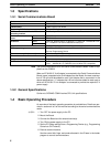
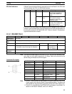
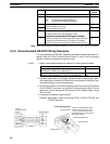
The TERM and WIRE switches are on the front panel of the Serial Communica-
tions Board. Refer to page 10 for a diagram of the Board.
When an RS-422/485 port is used, turn ON the switch if the Serial Communica-
tions Board is on the end of the transmission line. Refer to information on specific
serial communications modes for the ON/OFF settings.
Label Name Settings Factory setting
TERM Terminating
resistance switch
OFF:Terminating
resistance
OFF
ON: Terminating
resistance ON
OFF:Terminating
resistance
OFF
When an RS-422/485 port is used, set the switch to 2 when 2-wire connections
are used, and set the switch to 4 when 4-wire connections are used.
Label Name Settings Factory setting
WIRE 2-wire or 4-wire
switch
2: 2-wire
4: 4-wire
2: 2-wire
Note Host Link, no-protocol, and 1:1 Data Link modes cannot use 2-wire
RS-422A/485 communications. Always use 4-wire connections when using
RS-422A/485 communications for these serial communications modes. Refer
to 2-3 Wiring for connections.
Internal Circuits
Applicable Connectors
Recommended Cables
Terminating Resistance
Switch
2-Wire or 4-Wire Switch


