


8-2SectionConnections
116
6. With some PTs, timeout settings can be changed to eliminate some of the
communications errors. Refer to the operation manual for the PT for details.
This is true in both 1:1 and 1:N mode.
7. If more PTs are required by the system than allowed by the above restric-
tions in 1:N mode, connect the PTs in smaller groups to different ports.
8-2 Application Procedure
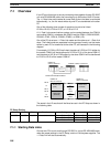
1, 2, 3... 1. Turn OFF the power supply to the PC.
2. Mount the Board.
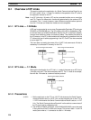
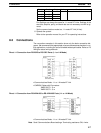
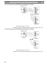
3. Connections
Connect the external devices using RS-232C or RS-422 cables. The TERM
and WIRE switches on the front panel of the Board must be set if the Board is
connected using the RS-422A/485 port.
The CPU Unit can be connected to a Programming Console, the CX-Pro-
grammer, or the CX-Protocol as required.
4. Turn ON power.
5. Set the PC Setup settings for the Serial Communications Board.
Use a Programming Console, the CX-Programmer, or the CX-Protocol to
set the settings in the PC Setup between DM 6550 and DM 6559.
Note The settings stored in these words are read constantly; the PC does
not need to be restarted or reset when changes are made to the set-
tings. They will be updated automatically as soon as they are
changed.
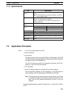
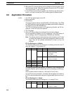
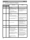
NT Link Settings for 1:N Mode
The following table shows the settings for connecting more than one PT
when the highest PT unit number is 5.
Port 1 Port 2 Bit(s) Setting Function
DM 6555 DM 6550
00 to 07 --- Not used.
08 to 11 5 (BCD) Maximum Programmable
Terminal unit number
1 to 7 (BCD)
NT Link in 1:N mode
12 to 15 5 Hex Communications mode
NT Link in 1:N mode
DM 6556 DM 6551 00 to 15
--- Not used.
DM 6557 DM 6552 00 to 15
DM 6558 DM 6553 00 to 15
DM 6559 DM 6554 00 to 15
Port Settings are always the same for 1:N-mode NT Links. Settings of the
start bits, stop bits, parity, and baud rate are not necessary and will be ig-
nored.
Set the communications mode to a 1:N-mode NT Link (5 Hex).
Up to 8 PTs can be connected in 1:N mode. Set the highest unit number of
the PTs to be connected as the maximum Programmable Terminal unit num-
ber.
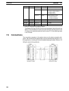
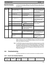
NT Link Settings for 1:1 Mode
The following table shows the settings for a 1:1-mode NT Link.
Port 1 Port 2 Bit(s) Setting Function
DM 6555 DM 6550
00 to 11 --- Not used.
12 to 15 4 Hex Communications mode
NT Link in 1:1 mode