


2-3SectionInstallation
20
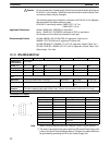
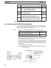
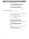
Pin Function Factory
setting
1 Not used. Always set this pin to ON. ON
2 Built-in terminating resistance setting
ON: Connects terminating resistance.
OFF: Disconnects terminating resistance.
ON
3
2/4-wire setting
OFF
4
2-wire: Set both pins to ON.
4-wire: Set both pins to OFF.
OFF
5
Transmission mode (See note)
Constant transmission: Set both pins to OFF.
Transmission performed when CTS signal in RS-232C
ON
6
Transmission performed when CTS signal in RS-232C
interface is at high level: Set pin 5 to OFF and pin 6 to ON.
Transmission performed when CTS signal in RS-232C
interface is at low level: Set pin 5 to ON and pin 6 to OFF.
OFF
Note When connecting to a CQM1H-series CPU Unit, turn OFF pin 5 and turn ON pin 6.
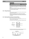
2-3-5 Recommended RS-232C Wiring Examples
It is recommended that RS-232C cables be connected as described below, es-
pecially when the Serial Communications Board is used in an environment
where it is likely to be subject to electrical noise.
1, 2, 3... 1. Always use shielded twisted-pair cables as communications cables.
Model Manufacturer
UL2464 AWG28x5P IFS-RVV-SB (UL-approved)
AWG28x5P IFVV-SB (not UL-approved)
Fujikura Ltd.
UL2464-SB (MA) 5Px28AWG (7/0.127) (UL-approved)
CO-MA-VV-SB 5Px28AWG (7/0.127) (not UL-approved)
Hitachi Cable,
Ltd.
2. Combine signal wires and SG (signal ground) wires in a twisted-pair cable.
At the same time, bundle the SG wires to the connectors on the Serial Com-
munications Board and the remote device.
3. Connect the shield of the communications cable to the Hood (FG) terminal
of the RS-232C connector on the Serial Communications Board. At the
same time, ground the ground (GR) terminal of the Power Supply Unit to
100 Ω or less.
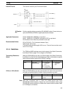
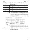
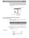
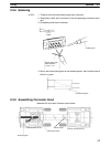
4. A connection example is shown below.
Example: Twisted-pair Cable Connecting SD-SG, RD-SG, RTS-SG, and
CTS-SG Terminals
Serial
Communications
Board
Remote device
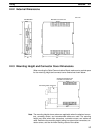
Actual Wiring Example
SG signal wires
Bundle the SG wires.
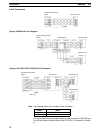
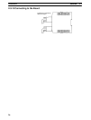
Aluminum foil
XM2S-0911-E
Pin Signal
Hood
Shield
Signal
Twist the braided shield to make
it thinner and connect to Pin No.
1 (FG). Cover this section with
heat-shrink tube to avoid contact
with other sections.
SD
RD
RTS
CTS
SG
FG
FG
RD
SD
CTS
RTS
SG
FG