


6-4SectionUsing No-protocol Communications
105
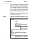
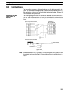
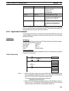
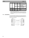
Port 1 Port 2 Function
IR 20100 to IR 20103 IR 20108 to IR 20111 Error Code
0: Normal operation
1: Parity error
2: Framing error
3: Overrun error
IR 20104 IR 20112 Communications Error Flag
IR 20107 IR 20115 Reception Overflow Flag (Turns ON
when data is received again before
the previous data is read with
RXD(––).)
IR 20200 to IR 20215 IR 20300 to IR 20315 Reception counter
Provides the number of bytes of
data received in 4-digit BCD (0 to
256).
The Port 1 Restart Bit (IR 20700) and Port 2 Restart Bit (IR 20701) can be turned
ON to initialize the serial communications ports. These bits will be turned OFF
automatically after the ports have been initialized.
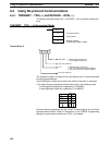
6-4-4 Application Example
This example shows how to send data from DM 0100 to DM 0104 (each word
contains 3454) to a computer and then store data received from the computer
starting at DM 0200.
Conditions
PC Settings
The following settings are made in the PC Setup before executing the program.
Communications mode: No-protocol
Port settings: Standard
Start code: None
End code: CR + LF
Other: Default settings
Computer Settings
Set the same communications parameters as the PC and prepare the programs
to send and receive data.
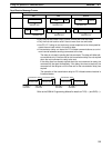
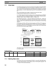
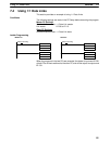
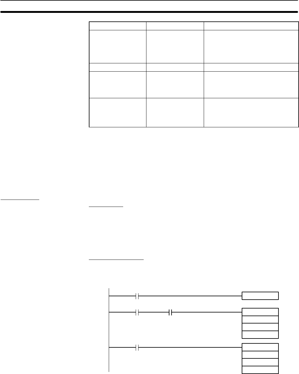
Ladder Programming
Transmission
Enabled Flag
Reception
Competed Flag
DIFU (13) 00101
00100
TXD
DM0100
#0100
#0010
00101
RXD
DM0200
#0100
#0256
20106
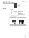
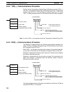
1, 2, 3... 1. When IR 00100 turns ON, the contents of DM 0100 to DM 0104 will be sent
with most significant bytes first from port 1 on the Serial Communications
Board if IR 20105 is ON (Transmission Enabled Flag).
The following data will be received at the computer:
34543454345434543454CRLF
2. When IR 20106 (Reception Competed Flag) turns ON, 256 bytes of data re-
ceived on port 1 on the Serial Communications Board will be read and
stored starting at DM 0200 with most significant bytes first.