


4-2SectionApplication Procedure
37
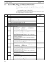
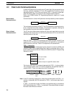
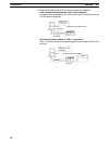
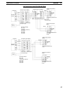
shown below. Perform other processing as required, such as setting
switches on the external device(s).
Serial Communications Board
Terminating resistance
ON
NT-AL001-E
Terminating resistance
ON, 5-V power supply
required
RS-232C
RS-422A
/485
3G2A9-AL001
RS-422A
/485
RS-232C
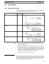
The CPU Unit can be connected to a Programming Console, the CX-Pro-
grammer, or the CX-Protocol as required.
4. Turn ON power.
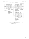
5. Set the PC Setup settings for the Serial Communications Board.
Use a Programming Console, the CX-Programmer, or the CX-Protocol to
set the settings in the PC Setup between DM 6550 and DM 6559.
Note The settings stored in these words are read constantly; the PC does
not need to be restarted or reset when changes are made to the set-
tings. They will be updated automatically as soon as they are
changed.
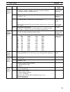
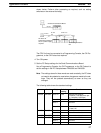
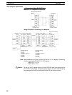
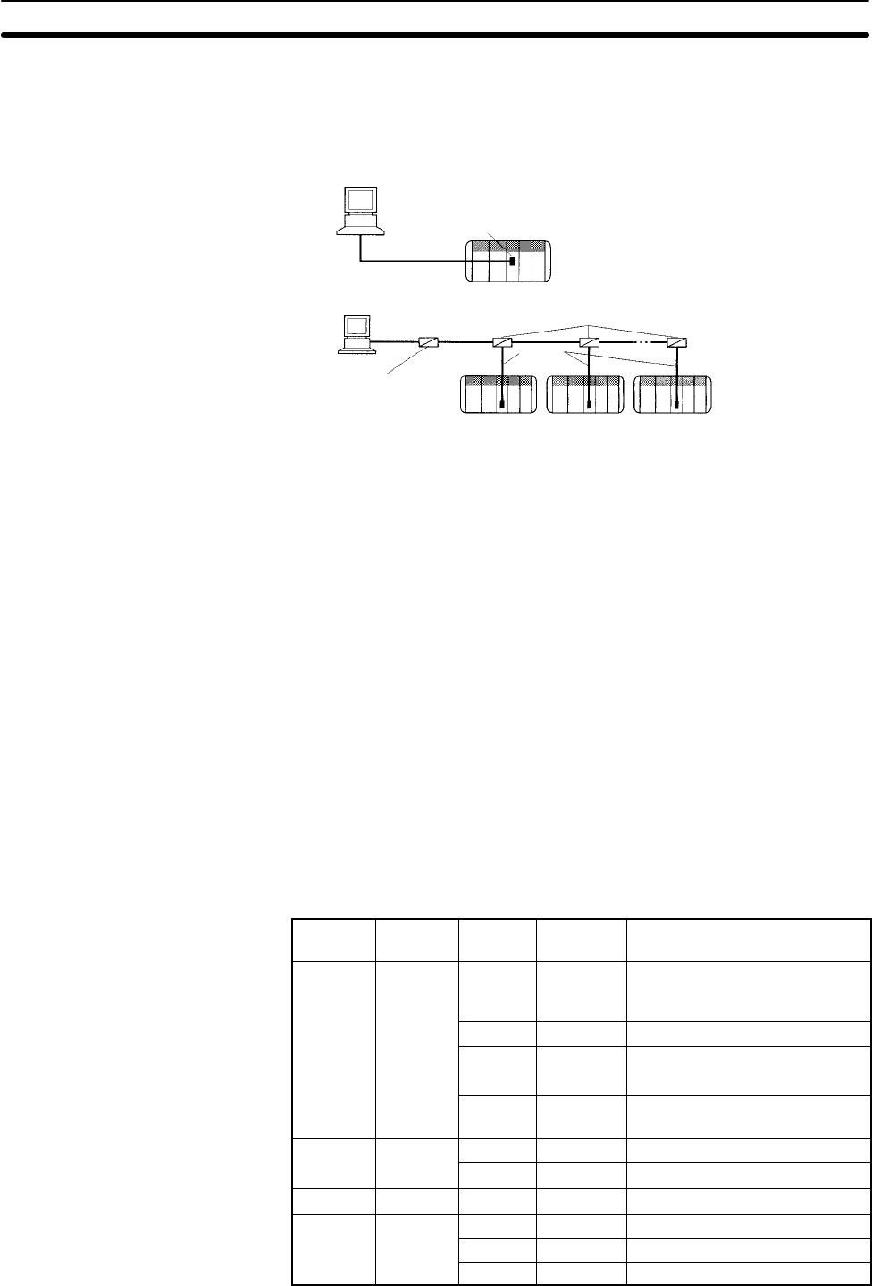
The following table shows the standard settings.
Port 1 Port 2 Bit(s) Default
setting
Function
DM 6555 DM 6550
00 to 03 0 Hex Standard port settings
(1 start bit, 7-bit data, even par-
ity, 2 stop bits, 9,600 bps)
04 to 07 0 Hex CTS control disabled
08 to 11 --- Not used.
12 to 15 0 Hex Communications mode
0: Host Link
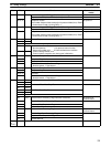
DM 6556 DM 6551
00 to 07 --- Baud rate: invalid
08 to 15 --- Frame format: Invalid
DM 6557 DM 6552 00 to 15 0000 Hex Transmission delay: 0 ms
DM 6558 DM 6553
00 to 07 00 BCD Node number 00
08 to 11 --- Not used.
12 to 15 --- Not used.