


2-1SectionInstallation
10
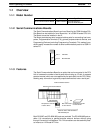
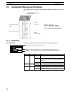
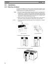
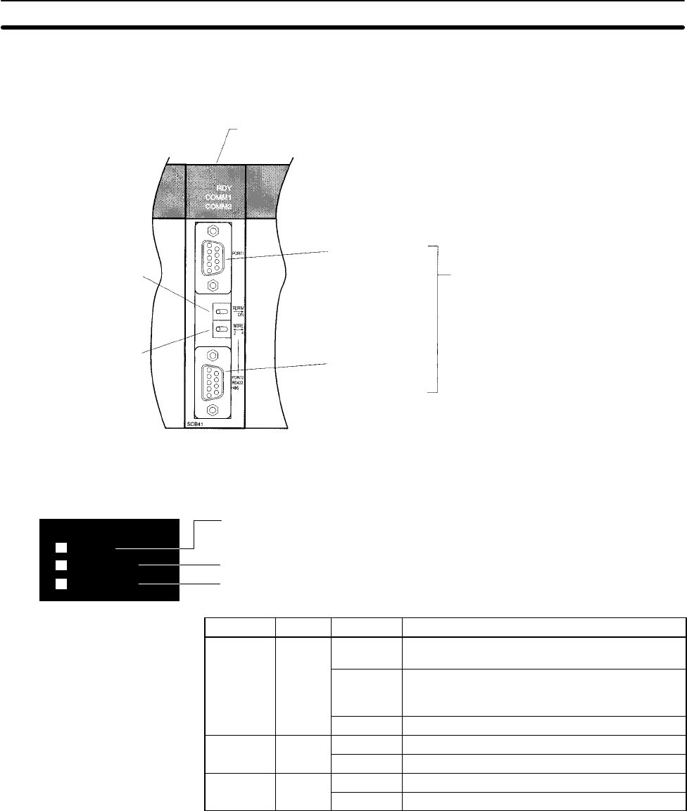
2-1 Component Names and Functions
The components of the Serial Communications Board are described in this sec-
tion.
Terminating resistance
switch
2-wire or 4-wire switch
Serial Communications Board
(Inner Board slot 1)
Port 1:
RS-232C
Port 2:
RS-422A/485
Applicable Connectors
Socket: XM2SA-0901 (OMRON)
Hood: XM2SA-0911-E (OMRON)
(Two of each are included with the Board)
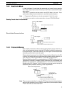
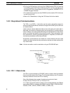
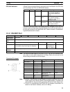
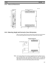
2-1-1 Indicators
There are three LED indicators on the Board, as described below.
COMM1: Lit when data is being sent or received on the RS-232C port (Yellow)
RDY
COMM1
COMM2
COMM2: Lit when data is being sent or received on the RS-442A/485 port (Yellow)
RDY: Lit when the Board is operational (green)
Indicator Color Status Meaning
RDY Green
Lit Operating normally, and protocol macro
preparations have been completed.
Flashing There is an error in the PC Setup settings for the
Board or in the protocol macros contained in the
Board.
Not lit A hardware error has occurred in the Board.
COMM1 Yellow
Flashing Port 1 is being used for sending or receiving.
Not lit Port 1 is not being used for sending or receiving.
COMM2 Yellow
Flashing Port 2 is being used for sending or receiving.
Not lit Port 2 is not being used for sending or receiving.
Board Indicators