


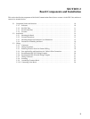

1-4SectionBasic Operating Procedure
8
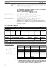
1-3 Specifications
1-3-1 Serial Communications Board
Device name Serial Communications Board
Model number CQM1H-SCB41
Classification CQM1H-series Inner Board
Supporting CPU Units CQM1H-CPU51/61
Number of mountable Boards/PC and
mounting location
One Board per PC maximum, must be in Inner Board slot 1
Serial communications
Port 1 RS-232C
ports
Port 2 RS-422A/485
Protocols
Port 1
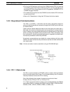
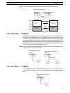
Host Link, protocol macro, no-protocol, 1:1 Data Link, 1:N-mode NT Link
Port 2
or 1:1-mode NT Link can be selected for each port.
Software interface with CPU Unit IR 200 to IR 207 (words for Inner Board slot 1)
PC Setup settings DM 6550 to DM 6559 (in read-only DM area in CPU Unit)
Set from Programming Device
Current consumption (see note) 200 mA max. at 5 V DC
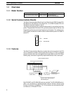
Dimensions 25 × 110 × 107 (mm) (W × H × D)
Weight 90 g max.
Standard accessories Socket: XM2SA-0901 (OMRON) (two included)
Hood: XM2SA-0911-E (OMRON) (two included, ESD compatible)
Note The current consumption is for one Serial Communications Board. Power is sup-
plied from the CQM1H
When an NT-AL001-E Link Adapter is connected to the Serial Communications
Board, power is supplied to the Link Adapter from the Board. A current consump-
tion of 150 mA must be added for each Link Adapter that is connected. In the
above specifications, “x” indicates that 150 mA must be added for each port to
which an NT-AL001-E Link Adapter is connected to provide the required 5-V
power supply.
1-3-2 General Specifications
Conform to SYSMAC CQM1H-series CPU Unit specifications.
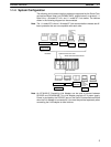
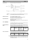
1-4 Basic Operating Procedure
An overview of the basic operating procedure is provided here. Details are pro-
vided in sections 4 to 8 of this manual according to the serial communications
mode.
1, 2, 3... 1. Turn OFF the power supply to the PC.
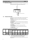
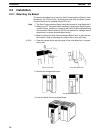
2. Mount the Board.
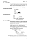
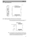
3. Connect the Board and the external device(s).
4. Turn ON the power supply to the PC.
5. Set the PC Setup settings from a Programming Device (e.g., Programming
Console or CX-Protocol).
6. Execute communications.
Use the control bits, flags, and words allocated in the IR area in the ladder
program to control communications.