


8-3SectionConnections
117
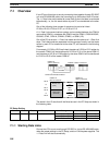
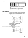
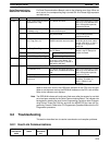
Port 1 FunctionSettingBit(s)Port 2
DM 6556 DM 6551 00 to 15
--- Not used.
DM 6557 DM 6552 00 to 15
DM 6558 DM 6553 00 to 15
DM 6559 DM 6554 00 to 15
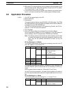
Port Settings are always the same for 1:1-mode NT Links. Settings of the
start bits, stop bits, parity, and baud rate are not necessary and will be ig-
nored.
Set the communications mode to a 1:1-mode NT Link (4 Hex).
6. Operate the system.
Refer to the operation manual for your PT for operating instructions.
8-3 Connections
The connection examples in this section show only the basic connection dia-
grams. We recommend that appropriate noise countermeasures be taken in ac-
tual applications, including the use of shielded twisted-pair cables. Refer to 2-3
Wiring for actual wiring methods.
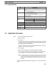
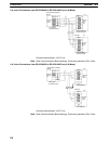
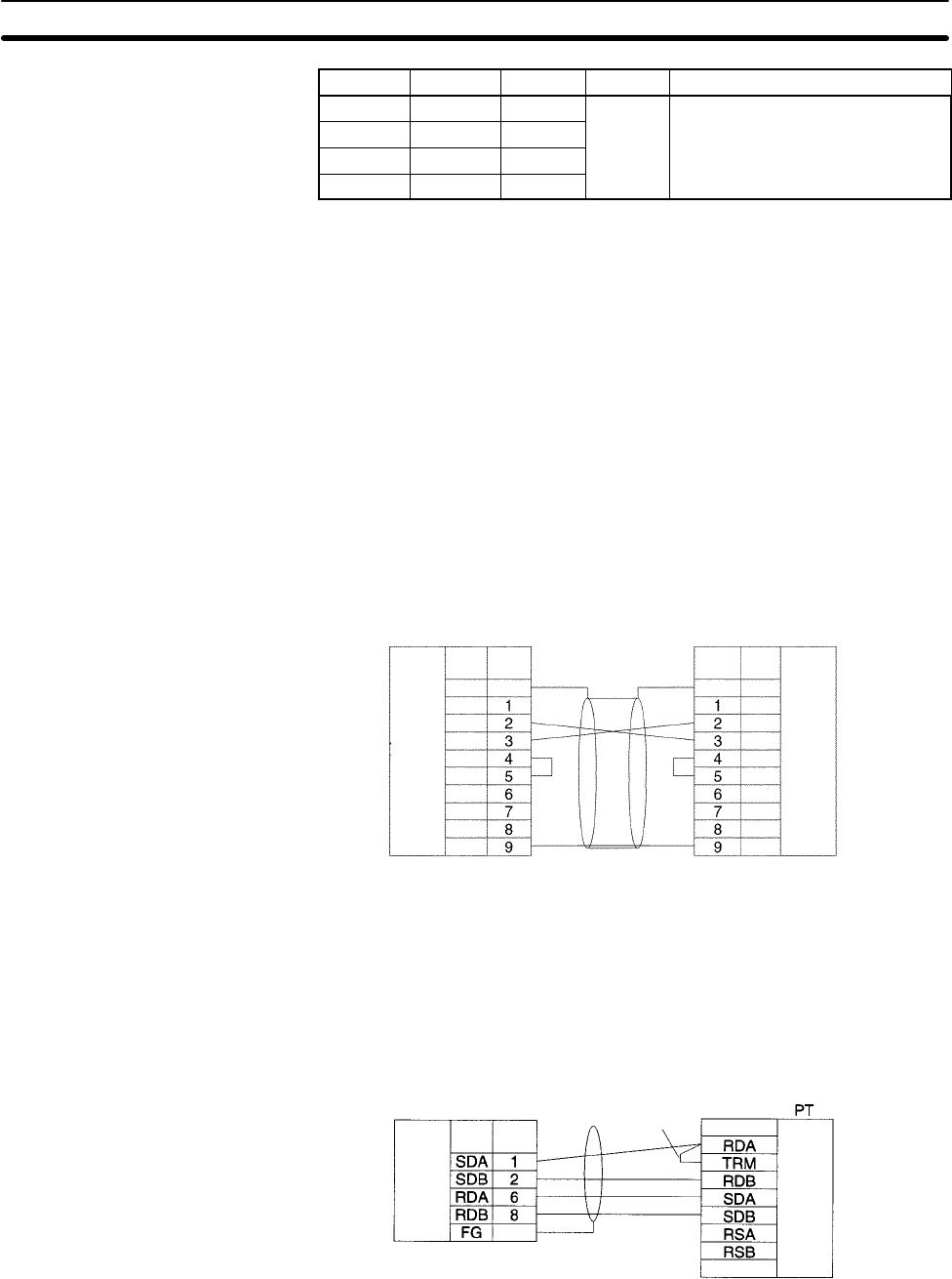
Direct 1:1 Connection from RS-232C to RS-232C Ports (1:1 or 1:N Mode)
Serial Communications
Board
PinSignal
PT
D-sub, 9-pin
connector (male)
RS-232C
Interface
Hood
Hood
D-sub, 9-pin
connector (male)
RS-232C
Interface
Pin Signal
FG
FG
SD
RD
RTS
CTS
5V
DSR
DTR
SG
FG
--
SD
RD
RTS
CTS
5V
--
--
SG
• Communications Mode: 1:1 or 1:N-mode NT Link
• OMRON Cables with Connectors:
XW2Z-200T-1: 2 m
XW2Z-500T-1: 5 m
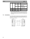
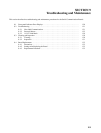
Direct 1:1 Connection from RS-422A/485 to RS-422A/485 Ports (1:1 or 1:N Mode)
Serial Communications
Board
PinSignal
Terminal block or
D-sub connector
Hood
D-sub, 9-pin
connector (male)
RS-422A/
485 Inter-
face
Signal
RS-422A/
485 Inter-
face
Functional ground
Short piece
• Communications Mode: 1:1 or 1:N-mode NT Link
Note Serial Communications Board settings: Terminating resistance ON, 4-wire.