3-2SectionPC Setup Settings
28
3-1 Overview
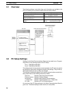
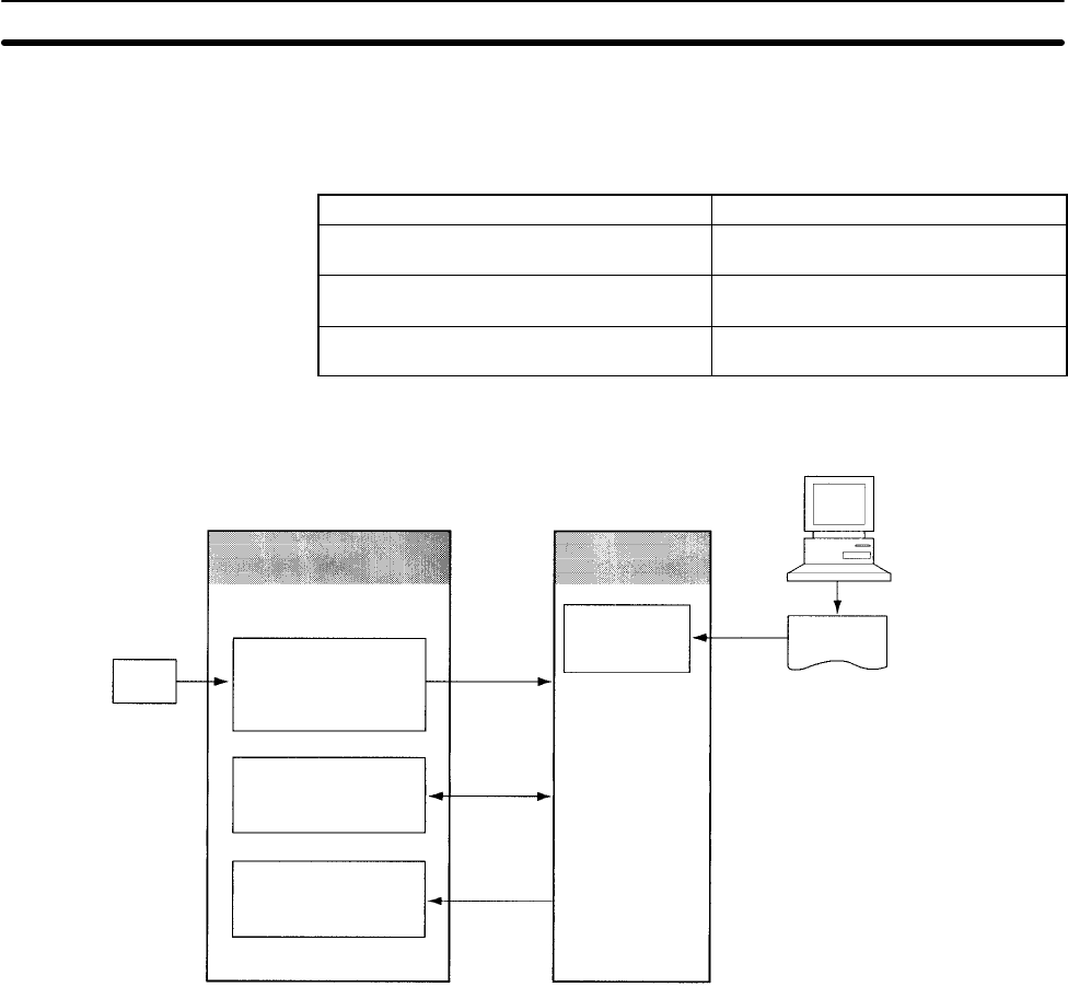
The following settings, control bits, flags, and information are available in the
CPU Unit memory for use with the Serial Communications Board.
Contents Addresses
PC Setup settings for the Serial
Communications Board
Port 1: DM 6555 to DM 6559
Port 2: DM 6550 to DM 6554
Control bits, flags, and status information
for the Inner Board slot 1
IR 200 to IR 207
Error flags and information for Inner
Boards
SR 25415: Inner Board Error Flag
AR 04: Inner Board Error Code
CPU Unit
Serial Communications Board
CX-Protocol (for protocol
macro mode operation)
Protocol
macro data
Flash memory
Protocol macro
data (for protocol
macro mode
operation)
Backup
battery
PC Setup settings
(DM 6550 to DM 6559)
Inner Board Slot 1
Area
(IR 200 to IR 207)
Inner Board Error Flag
and Error Code
(SR 25415 and AR 04)
Read
constantly
Refreshed
3-2 PC Setup Settings
Settings for the Serial Communications Board can be made from a Program-
ming Device in the following words of the PC Setup.
Port 1: DM 6555 to DM 6559
Port 2: DM 6550 to DM 6554
The settings stored in these words are read constantly; the PC does not need to
be restarted or reset when changes are made to the settings. They will be up-
dated automatically as soon as they are changed.
The settings in these words depend on the serial communications mode that is
being used. Refer to the following sections for details.
Host Link: Section 4 Host Link Communications
Protocol macros: Section 5 Protocol Macros
No-protocol: Section 6 Non-protocol Communications
1:1 Data Links: Section 7 Communications for 1:1 Data Links
NT Links: Section 8 NT Link Communications
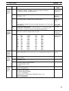
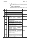
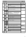
An overview of the PC Setup settings for the Serial Communications Board is
given next. The default setting for each word is all zeros (0000).


