


9-2SectionBoard Replacement
123
Serial com-
munications
mode
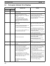
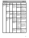
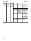
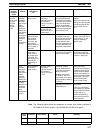
RemedyCauseI/O memoryStatus
information,
etc.
Indicator
status
Serial commu-
nications mode
is set to Host
Link. (Contin-
ued)
The COMMj
indicators are
flashing, but
the response
has not been
returned to the
There is a
transmission
error.
The error code in
IR 20100 to
IR 20103 for port 1
or IR 20108 to
IR 20111 for port 2
is 1 (parity error), 2
The communica-
tions conditions
and baud rate do
not match the set-
tings at the host.
Review the PC Setup, the
host’s settings, and pro-
gram (such as commands
and frame format) based
on the response and the
error code.
host.
(framing error), or 3
(overrun error).
There is noise in-
terference.
Use shielded twisted-pair
cables.
Lay power lines separate-
ly using ducts.
Review the installation
environment to reduce
noise interference.
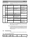
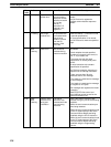
The COMMj
indicators are
flashing, and
an error re-
sponse has re-
There is no
transmission
error.
IR 20100 to
IR 20103 or
IR 20108 to
IR 20111 are
0 Hex.
A command was
sent from the host
with incorrect pa-
rameters.
Review the host’s settings
and program (such as pa-
rameter settings) based
on the response contents.
turned to the
host.
There is a
transmission
error.
The error code in
IR 20100 to
IR 20103 for port 1
or IR 20108 to
IR 20111 for port 2
is 1 (parity error), 2
(framing error), or 3
(overrun error).
The communica-
tions conditions
and baud rate do
not match the set-
tings at the host.
Review the PC Setup, the
host’s settings and pro-
gram (such as commands
and frame format) based
on the response, and the
error code in IR 20100 to
IR 20103 or IR 20108 to
IR 20111.
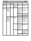
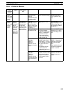
The COMMj
indicators are
flashing, but
sometimes
there is no re-
sponse re-
turned.
There is an
intermittent
transmission
error.
The error code in
IR 20100 to
IR 20103 for port 1
or IR 20108 to
IR 20111 for port 2
is 1 (parity error), 2
(framing error), or 3
(overrun error).
The baud rate is
outside the allow-
able range, and the
stop bits do not
match, causing the
bits to be out of
alignment.
Review the PC Setup.
Review the host’s settings
and program (such as
baud rate and frame for-
mat).
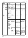
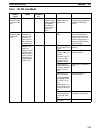
Terminating resist-
ance switch
(TERM) status
Cables are incor-
rectly connected.
The RS-422A/485
port 2-wire/4-wire
terminating resist-
ance setting is in-
correct.
Adapters such as
the NT-AL001-E
are incorrectly
wired or the termi-
nating resistance is
incorrectly set.
Check the wiring.
Turn ON the terminating
resistance of the Serial
Communications Board
and the last node by us-
ing the terminating resist-
ance switch. Turn OFF
the terminating resistance
of other nodes.
The error code in
IR 20100 to
IR 20103 for port 1
or IR 20108 to
IR 20111 for port 2
is not 0.
Transmission er-
rors are occurring
that are caused by
noise interference.
Use shielded twisted-pair
cables.
Lay power lines separate-
ly using ducts.
Review the installation
environment to reduce
noise interference.