


2-3SectionWiring
19
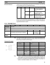
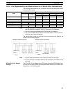
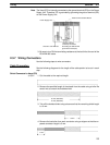
2-3-4 Port Applicability and Restrictions for 2-Wire/4-Wire Connections
The following table shows the port connections that can be used for each serial
communications mode.
Serial communications
RS-232C port RS-422A/485 port
mode
1:1 1:N
4-wire 2-wire
1:1 1:N 1:1 1:N
Host Link OK OK (See
note 2)
OK OK No No
Protocol macros OK OK OK OK OK
No-protocol OK OK OK No No
1:1 Data Links OK No OK No No No
1:N-mode NT Links OK OK OK OK OK
1:1-mode NT Links OK No OK No No No
Note 1. The 1:N connection method can be used by converting between RS-232C
and RS-422A/485 through NT-AL001-E Converting Link Adapters.
2. Use 4-wire connections between the Converting Link Adapters.
3. The 2-wire RS-422A/485 connections cannot be used for Host Link commu-
nications. Use 4-wire connections.
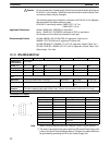
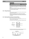
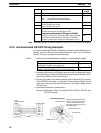
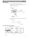
The transmission circuits for 2-wire and 4-wire connections are different, as
shown in the following diagram.
Example of 4-Wire Connections
Example of 2-Wire Connections
2/4-wire switch
(DPDT)
Board
2/4-wire switch
(DPDT)
Board
Not connected
Other Unit
Other UnitOther Unit
Other Unit
Note 1. Use the same transmission circuit (2-wire or 4-wire) for all nodes.
2. Do not use 4-wire connections when the 2/4-wire switch on the Board is set
to 2-wire.
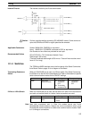
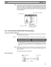
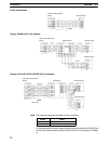
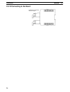
The NT-AL001-E Link Adapter has a DIP switch for setting RS-422A/485 com-
munications conditions. When connecting the Board, refer to the DIP switch set-
tings shown in the following table.
NT-AL001-E Link Adapter
Settings