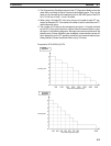
7-3SectionOverview
110
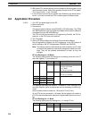
Port 1 Port 2 Bits Setting Function
DM 6555 DM 6550
00 to 07 --- Not used.
08 to 11 0 Hex Link words for 1:1 Data Link
0: LR 00 to LR 63 (default)
1: LR 00 to LR 31
2: LR 00 to LR 15
12 to 15 3 Hex Communications mode
2: 1:1 Data Link slave
3: 1:1 Data Link master
DM 6556 DM 6551 00 to 15 --- Not used.
DM 6557 DM 6552 00 to 15 --- Not used.
DM 6558 DM 6553 00 to 15 --- Not used.
DM 6559 DM 6554 00 to 15 --- Not used.
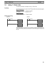
6. Write and executed the ladder program.
The Always ON Flag (SR 25313) can be use to program instructions such as
MOV(21) to write data to be sent to the other PC to the sending words in the
LR area and to read data received from the other PC in the receiving words
in the LR area.
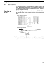
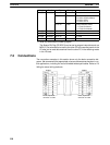
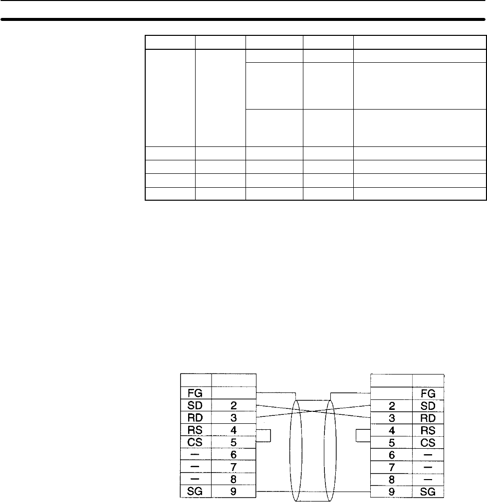
7-3 Connections
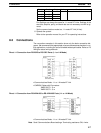
The connection examples in this section show only the basic connection dia-
grams. We recommend that appropriate noise countermeasures be taken in ac-
tual applications, including the use of shielded twisted-pair cables. Refer to 2-3
Wiring for actual wiring methods.
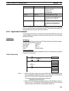
CQM1H
Signal Pin
D-sub, 9-pin male
connector on cable
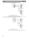
CQM1H
SignalPin
Connector edge
D-sub, 9-pin male
connector on cable
Connector edge


