


7-2SectionUsing 1:1 Data Links
109
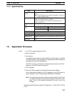
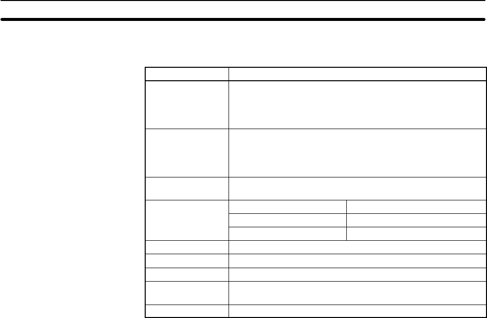
7-1-2 Specifications
Item Specification
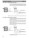
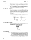
Connection
method
Connection of 2 PCs through their RS-232C ports (prepared
cable).
Note RS-422A/485 ports can also be connected if a 4-wire con-
nection method is used.
Applicable PCs CQM1H, CQM1, CPM1, CPM1A, CPM2A, CPM2C, or
SRM1(-V2), C200HX/HG/HE, C200HS
There are restrictions in the number of words that can be
linked for some PCs.
Number of nodes
linked
2
Number of words
64 words, LR 00 to LR 63 32 words sent per node
linked
32 words, LR 00 to LR 31 16 words sent per node
16 words, LR 00 to LR 15 8 words sent per node
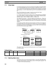
Linked words One of three groups listed above
Link word setting PC Setup in master PC
Order of allocation Words allocated to master PC first and then to slave PC.
Startup method Automatic startup after turning ON power to master and slave
PCs.
Status flags None
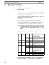
7-2 Application Procedure
1, 2, 3... 1. Turn OFF the power supply to the PC.
2. Mount the Board.
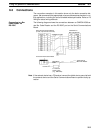
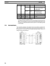
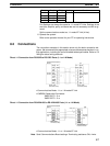
3. Connections
Connect the external devices using RS-232C or RS-422 cables. The TERM
and WIRE switches on the front panel of the Board must be set if the Board is
connected using the RS-422A/485 port.
The CPU Unit can be connected to a Programming Console, the CX-Pro-
grammer, or the CX-Protocol as required.
4. Turn ON power.
5. Set the PC Setup settings for the Serial Communications Board.
Use a Programming Console, the CX-Programmer, or the CX-Protocol to
set the settings in the PC Setup between DM 6550 and DM 6559.
Note The settings stored in these words are read constantly; the PC does
not need to be restarted or reset when changes are made to the set-
tings. They will be updated automatically as soon as they are
changed.
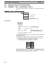
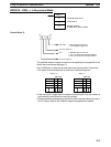
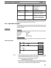
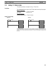
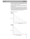
The following table shows the master PC settings for a 1:1 Data Link for LR 00 to
LR 63.