4-2SectionConnections
36
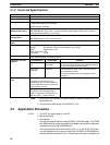
4-1-2 Host Link Specifications
Item Description
Communications mode Half-duplex (Full-duplex for slave-initiated communications)
Synchronization Start-stop (asynchronous mode)
Baud rate (see note 1) RS-232C port and RS-422A/485 ports:
1,200/2,400/4,800/9,600/19,200 bps
Default setting: 9,600 bps
Communications
distance (see note 1)
RS-232C port: 15 m max. (see note 2)
RS-442A/485 port: 500 m max. (The total combined cable length is 500 m max. T-branch
lines must be a maximum of 10 m long.)
Connection
configuration
RS-232C port: 1:1 (1:N (N = 32 Units max.) is possible using an Converting Link Adapters.)
RS-422A/485 port: 1:N (N = 32 Units max.)
Number of connected
Units
32 Units max. (unit numbers 0 to 31; unit number 0 is set for 1:1 connection)
Frame structure C-mode Host Link commands
Header: @, address: (Host Link unit number) 0 to 31 (BCD)
Data: Header code + text
Error check code: FCS
Terminator: *+CR
Error check codes Vertical parity: Even, odd. or none
FCS (horizontal parity converted to ASCII)
Command flow and
Command flow Commands Contents
support
Host computer to
PC
C-mode Host Link
commands
1:1 or 1:N communications with directly connected
PCs (The specified frame format must be prepared
on the host computer and then sent.)
PC to host
computer
Data only Communications using TXD(––) from CPU Unit.
No response from host.
Connection between the host computer and PC
must be 1:1.
Transmission delay
time
Host computer to PC
The delay is from the return of a
response by the PC until a response
can be returned to the next command
received from the host.
0 to 99,990 ms (set in PC Setup in 10-ms units)
PC to host computer
The delay is from the beginning of
TXD(––) execution until execution of
the next TXD(––) can be started.
Note 1. Confirm the baud rates and communications distance supported by con-
nected devices.
2. The maximum cable length for RS-232C is 15 m.
4-2 Application Procedure
1, 2, 3... 1. Turn OFF the power supply to the PC.
2. Mount the Board.
3. Connections
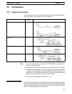
Connect the external devices using RS-232C or RS-422 cables. The TERM
and WIRE switches on the front panel of the Board must be set if the Board is
connected using the RS-4522A/485 port.
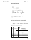
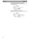
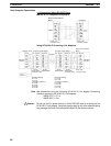
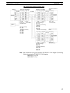
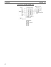
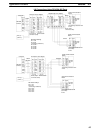
The host computer can be connected to a PC 1:1, or NT-AL001-E Convert-
ing Link Adapters can be used to convert from RS-232C to RS-422A/485 to
connect the host computer to PCs 1:N. Standard connection examples are


