


!
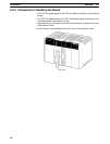
2-1SectionInstallation
12
Caution Do not connect the 5-V power supply of pin 6 to any external device other than an
NT-AL001-E Link Adapter. Otherwise, the external device and the Serial Com-
munications Board may be damaged.
The following cables are provided for connection to NT-AL001-E Link Adapters.
We recommend that these cables be used.
NT-AL001-E connecting cables: XW2Z-070T-1 (0.7 m)
XW2Z-200T-1 (2 m)
Socket: XM2A-0901 (OMRON) or equivalent
Hood: XM2S-0911-E (OMRON, conforms to ESD) or equivalent
One Socket and one Hood are provided for each port.
UL2464 AWG28 5P IFS-RVV-SB (UL-approved, Fujikura Ltd.)
AWG28 5P IFVV-SB (not UL-approved, Fujikura Ltd.)
UL2464-SB (MA) 5P 28AWG (7/0.127) (UL-approved, Hitachi Cable, Ltd.)
CO-MA-VV-SB 5P 28AWG (7/0.127) (not UL-approved, Hitachi Cable, Ltd.)
Cable length: 15 m max.
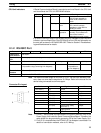
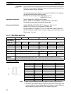
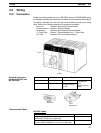
2-1-3 RS-422A/485 Port
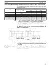
Protocol Host Link No-protocol Protocol macros 1:1 Data Links 1:N NT Links 1:1 NT Links
Communica-
tions method
Half-duplex
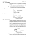
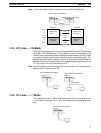
4-wire, 1:1 OK OK OK OK OK OK
4-wire, 1:N OK OK OK No OK No
2-wire, 1:1 No No OK No OK No
2-wire, 1:N No No OK No OK No
Synchroniza-
tion
Start-stop synchronous (asynchronous)
Baud rate 1,200/2,400/4,800/9,600/ 19,200 bps 19,200 bps 38,400 bps 19,200 bps
Connections 1:N (N: 32 Units max.) 1:1 1:N (N: 8 Units
max.)
1:1
Transmission
distance
500 m max.
(The total combined cable length is 500 m max. T-branch lines must be a maximum of 10 m long.)
Interface Complies with EIA RS-485
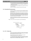
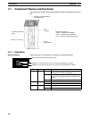
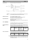
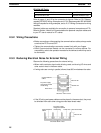
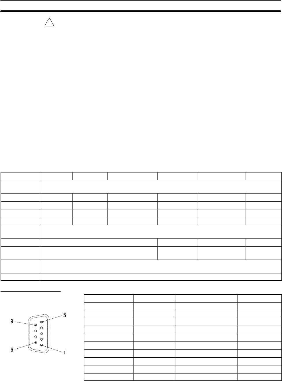
Connector Pin Layout
Pin No. Abbreviation Signal name I/O
1 (See note 1) SDA Send data – Output
2 (See note 1) SDB Send data + Output
3 NC Not used ---
4 NC Not used ---
5 NC Not used ---
6 (See note 1) RDA Receive data – Input
7 NC Not used ---
8 (See note 1) RDB Receive data + Input
9 NC Not used ---
Shell (See note 2) FG Shield ---
Note 1. When 2-wire connections are used, use pins 1 and 2, or pins 6 and 8.
2. The shell is connected to the ground terminal (GR) of the Power Supply Unit
inside of the Serial Communications Board. Therefore, the cable shield can
be grounded by grounding the GR of the Power Supply Unit.
Applicable Connectors
Recommended Cables