


4-4SectionApplication Procedure
49
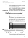
480 Q=ASC(MID$(RESPONSE$,I,1)) XOR Q
490 NEXT I
500 FCSD$=HEX$(Q)
510 IF LEN(FCSD$)=1 THEN FCSD$=”0”+FCSD$ ’FCS result
520 IF FCSD$<>FCSP$ THEN FCSCK$=”ERR”
530 PRINT”FCSD$=”;FCSD$,”FCSP$=”;FCSP$,”FCSCK$=”;FCSCK$
540 RETURN
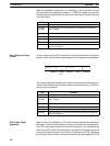
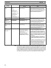
Note 1. Normal reception data includes the FCS, delimiter or terminator, and so on.
When an error occurs in transmission, however the FCS or some other data
may not be included. Be sure to program the system to cover this possibility.
2. In this program example, the CR code (CHR$(13)) is not entered for RE-
SPONSE$. When including the CR code, make the changes in lines 430
and 450.
This example shows a program for using the RS-232C port in the Host Link
mode to transmit 10 bytes of data (DM 0000 to DM 0004) to a computer. From
DM 0000 to DM 0004, “1234” is stored in every word.
The default values are assumed for all of the PC Setup (i.e., the RS-232C port is
used in Host Link mode, the node number is 00, and the standard communica-
tions parameters are used.)
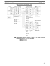
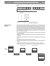
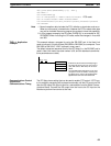
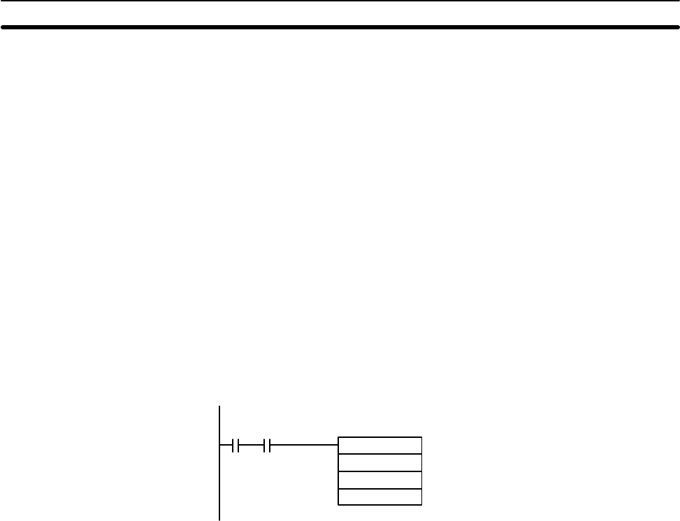
@TXD(––)
DM 0000
#0100
#0010
00100 20105
If SR 20105 (the Transmission Ready Flag) is
ON when IR 00100 turns ON, ten bytes of
data (DM 0000 to DM 0004) will be trans-
mitted.
The transmitted data will appear on the host
computer’s screen as follows, assuming the
text being sent is “1234” in all specified words:
@00EX1234123412341234123459*CR
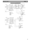
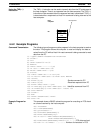
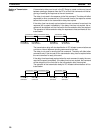
The PC Setup has a setting that can be used to enable CTS control. If CTS con-
trol is enabled, processing will be placed on standby until the CS input turns ON
after the RS output ON signal is sent for a transmission from the Serial Commu-
nications Board. Connect the RS output from the host to the CS input on the
Board and perform flow control at the host.
TXD(––) Application
Example
Communications Control
Signals and
Communications Timing