


NEAX2400 IPX Feature Programming Manual
Page 784 NDA-24297, Issue 1
U-1 Uniform Call Distribution (UCD)
Programming (cont’d)
STEP 7: ADSL -AssignUCDBOkey;AssignSN=0(Idle),3(CalledStationBusy)andFKY=19(UCDBusy
Out).
This command is used for assigning a function to each soft key.
STEP 8: ATRF - Assign Traffic Measurement Order.
TYPE: Type of Traffic Measurement
INTERVAL: Output Interval must be assigned in units of ten minutes (range is from 30-120 minutes),
or data “0” must be assigned, which is the instruction for assigning output time.
FROM-TO-: Measurement time is to be designated.
TIME: Output Time
TYPE: 1-11
1: Terminal Traffic Measurement
2: Route Traffic Measurement
3: Station Peg Count
4: Attendant Console Peg Count
5: Route Peg Count
6: Service Peg Count
8: UCD Route Peg Count
9: UCD Group Peg Count
10: UCD Station Peg Count
11: CCIS Traffic Count
STEP 9: DTF3 - Display of Traffic Data 3
TYPE: Type of Traffic Measurement
8: UCD Route Peg Count
9: UCD Group Peg Count
10: UCD Station Peg Count
STEP 10: AUCD/AUCDL - Assign the related data for the UCD group, if necessary. Assign the tenant number/
user group number and the station number/telephone number of the UCD controlling station, QTH
ACT, QTH for the UCD PEG COUNT, CWT for CALL WAITING LAMP UCD [C-76], and MCI for
MESSAGE CENTER INTERFACE [M-26].
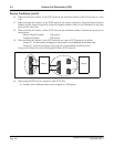
STEP 11: APHN - Assign Phantom Number to each UCD controlling station (if necessary).
TN: Tenant number
REAL STN: Station number of the controlling station
PH: Phantom number mode
0 = Used individually
1 = Used as the UCD group number (UCD hunting to be activated)
PHSTN: Phantom station number