NEAX2400 IPX Feature Programming Manual
Page 40 NDA-24297, Issue 1
A-29 Authorization Code - Tie Line Incoming Routes
Programming (cont’d)
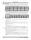
Note: Procedure 1 is not available with AUTHORIZATION CODE - TIE LINE INCOMING ROUTES. For
example:
45 - 26428 - 623423 - 9-1-617-555-2323
(ACC) (AUTH CODE) (ACCOUNT CODE) (DESTINATION CODE)
ASPA ACC = 45 NND = 8 (ACC+ACCOUNT CODE)
For SRV = LCR (Least Cost Route Selection) / LCRS (Register Sender LCR), if operating Procedure 2 is
used, (dialing the AUTHORIZATION CODE after the number dialed), assign data “1” to the AH parameter
when programming the LCR(S) access code. Therefore, operating Procedure 2 is only available with
LEAST-COST ROUTING - 3/6 DIGIT [L-5].
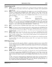
STEP 4: ASFC - For stations allowed AUTHORIZATION CODE - TIE LINE INCOMING ROUTES, assign a
Class of Service that allows SFI 27.
STEP 5: AMND - For Tenant 0, assign the Destination Code (DC) as the first digit of all AUTHORIZATION
CODEs and the Maximum Necessary Digits (MND) of the AUTHORIZATION CODE. For the above
example, a DC of 2 is assigned with an MND of 7. The MND value will include the digits added by the
Checksum method.
STEP 6: AATC - Assign the TN, Digit Code (DC) (the actual code itself), the AUTHORIZATION CODE
Restriction (ACR) as data “1”, and Service Feature Class (SFC) and Route Restriction Class (RSC). If
ACR is assigned as data 2, Allowed: RSC and SFC parameters are not programmed. (SFC parameters
are not operational.)
STEP 7: LATC - List all the AUTHORIZATION CODES. This is the simplest way to determine what digits
have been added to the system with the Checksum method. This is not required if the Checksum
method is not used.
TIE Line Programming
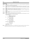
STEP 8: ARTD - Assign the TIE Line routes as shown below:
RT:1
1-OSGS :2 2-ONSG :3 5-TF :1 6-TCL :1 7 L/T :1
8-RLP :2 15-LSG :1
STEP 9: ATRK - Assign the LEN, TIE Line Route Number, Trunk Number, and Tenant Number.
STEP 10: MBTK - Assign the Make Idle status to the TIE Line Trunks.
STEP 11: ANPD- Assign a number level for trunk access. Assign Connection Index, CI = N, H; Normal (N) and
Hooking (H). Number of Necessary Digits is usually 1 or 2. Busy Lamp Field is not activated.
STEP 12: ASPA - Assign the access code as assigned in ANPD. Type of Service, SRV = OGC (Outgoing Call)
Outgoing Trunk. Assign the route number associated with this access code.
STEP 13: ARSC - The Route Restriction Class (RSC) must be constructed to allow the station access to the
involved routes.
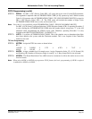
FCCS Programming
This data setting describes only the additional or replacement commands used to activate FCCS
services. When used as an FCCS feature, these commands replace the non-network commands (for
example, AAED is replaced by AAEDN). Note that the data setting for FCCS service varies depending
on the node.
Note
STEP 1: ANPDL - Reserve a number level for feature access. Assign for normal (N), Hooking (H), and Busy
(B) (if applicable to any feature in this level). Assign NND in accordance with a predetermined
numbering plan.


