MEMORY INTERFACING
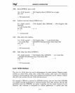
tRR:
Read
(EPRD#)
pulse width
(10 x CLK2 period) - PLD
RegOut
Skew
(EPRD#
low to high)
(10 x 25) - 4
= 246 nanoseconds
tRA: Address hold after
Read
(EPRD#
rise)
(0 x CLK2 period) - PLD RegOut Max
(EPRD#)
+
PLD
RegOut Min
(ALEIO)
+ Latch Enable Min
(0 x 25) - 6 + 2
+ 5
1 nanoseconds
tAD:
Data
delay from Address
(12 x CLK2 period)
- xcvr. prop. Max
(12 x 25)
- 6
= 258 nanoseconds
-
PLD
RegOut
Max - Latch Enable Max
- Intel386
DX
Microprocessor
Data
Setup Min
-
12
-
13
-11
tRD:
Data
delay from
Read
(EPRD#)
(10 x CLK2 period) - PLD
RegOut
Max
(EPRD#)
- xcvr. prop Max
- Intel386
DX
Microprocessor
Data
Setup Min
(10 x 25) - 6 - 6
-11
= 227 nanoseconds
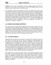
6.2.8 16-Bit Interface
The
use
of
a 16-bit data bus can
be
advantageous for some systems. Memory imple-
mented as 16-bits wide rather than 32-bits wide reduces chip count. I/O addresses
located
at
word boundaries rather
than
doubleword boundaries can
be
software compat-
ible with some systems that use 16-bit microprocessors.
For
example, if BS16#
is
asserted for
EPROM
accesses, only two byte-wide
EPROMs
are needed. Overall performance
is
reduced because 32-bit data accesses
and
all code
prefetches from
the
EPROMs
are slower (requiring two bus cycles instead
of
one).
However, this reduction
is
acceptable in certain applications. A system
that
uses
6-11


