CACHE SUBSYSTEMS
The main memory
is
updated using buffered write-through. Implementing buffered
write-through
is
slightly more complicated than unbuffered write-through, but it has the
advantage that the processor can continue to run while the
DRAM
write
is
taking place.
In contrast, write-back
is
significantly more complicated, but may
be
beneficial if main
memory traffic must
be
kept to a minimum (as in multiprocessor systems, for example).
The line size
is
four bytes, which
is
most convenient for the 32-bit data bus of the
Intel386
DX
microprocessor.
An
8-byte line size would transfer twice
as
much data for
every DRAM access, but would require a wider bus
as
well
as
more SRAMs, DRAMs,
and transceivers.
In such cases, one must weigh the additional cost against the additional
performance.
The cache in this example stores both code and data, rather than only code. Code-only
caches are easier to implement because there are no write accesses. They can be useful
if data accesses are infrequent. In general, however, most programs make frequent data
accesses. The code prefetch function of the Intel386
DX
microprocessor makes the
access time for code less critical to overall performance, since opcodes returned to the
processor more quickly may only reside in the code queue longer.
7.6.2 Example Cache Memory Organization
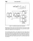
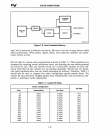
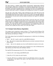
The example cache
is
organized
as
shown in Figure 7-9.The cache holds
64
Kbytes (16K
locations
of
4-byte blocks)
of
data and code and requires 16K 16-bit tag locations. The
main memory can hold up to 2 Gbytes.
The 32-bit address from the Intel386
DX
microprocessor
is
divided into the following
three fields:
• Select - Bit A31
is
used to select the cache/DRAM subsystem.
• Tag - Bits A30-A16 identify which
DRAM
location currently
is
associated with each
cache location.
• Index - Bits
A15~A2
identify one of the 16,384 doubleword locations in the cache.
Each doubleword location of the cache can be occupied
by
one of the 32,768 blocks from
main memory (one block from each 64-kilobyte section).
The Intel386
DX
microprocessor bits A31-A2 are interpreted
as
follows:
1.
Select bit
A31
is
low
during cache/DRAM cycles.
2.
Index bits A15-A2 select the cache location.
3.
Tag bits A30-A16 are compared with the tag information stored in the cache
to determine of the block in the cache
is
the block needed
by
the Intel386
DX
microprocessor.
7-14


