PHYSICAL DESIGN AND DEBUGGING
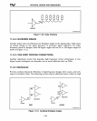
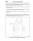
as other terminations. A common solution
is
to place active terminations
at
both ends of
the bus. This helps to maintain the uniform drive levels along the entire length of the
bus, and it reduces crosstalk and ringing.
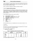
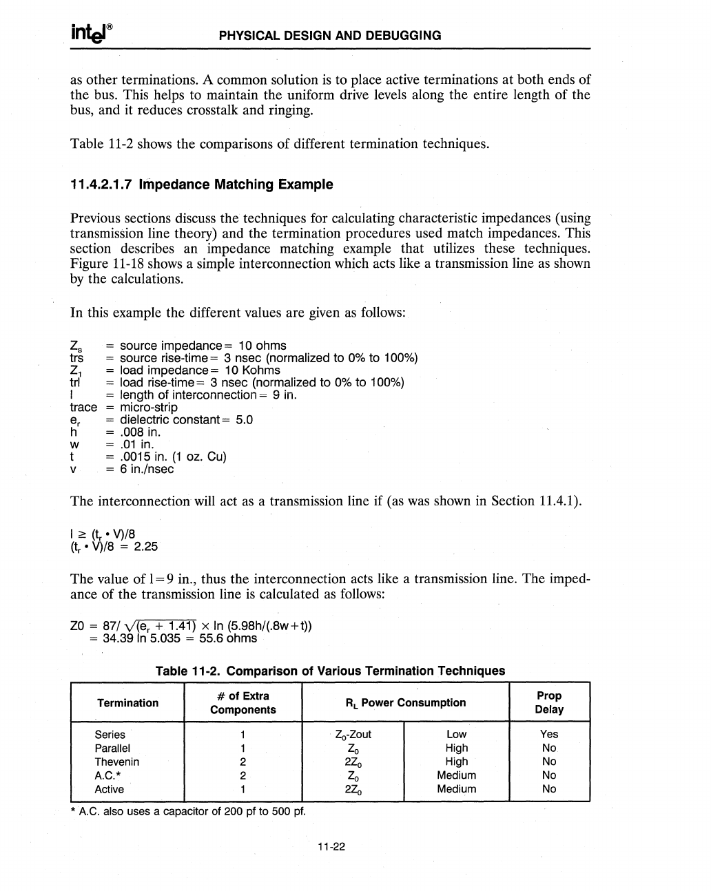
Table
11-2
shows the comparisons of different termination techniques.
11.4.2.1.7 Impedance Matching Example
Previous sections discuss the techniques for calculating characteristic impedances (using
transmission line theory) and the termination procedures used match impedances. This
section describes an impedance matching example that utilizes these techniques.
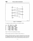
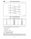
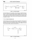
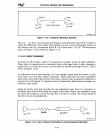
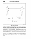
Figure
11-18
shows a simple interconnection which acts like a transmission line
as
shown
by
the calculations.
In this example the different values are given
as
follows:
Zs
= source impedance = 10 ohms
trs
= source rise-time = 3 nsec (normalized to 0% to 100%)
Z1
= load impedance =
10
Kohms
trl = load rise-time = 3 nsec (normalized to 0% to 100%)
I = length of interconnection = 9 in.
trace
= micro-strip
e
r
= dielectric constant = 5.0
h = .008 in.
w =
.01
in.
t = .0015 in.
(1
oz.
Cu)
v = 6 in./nsec
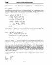
The interconnection
will
act
as
a transmission line if (as
was
shown in Section 11.4.1).
I
0::
(tr·
V)/8
(tr
• V)/8 = 2.25
The value
of
1=9
in., thus the interconnection acts like a transmission line. The imped-
ance of the transmission line
is
calculated
as
follows:
ZO
= 87/
v(e
r
+ 1.41) x
In
(5.98h/(.8w+t))
= 34.39
In
5.035 = 55.6 ohms
Table
11·2.
Comparison
of
Various
Termination
Techniques
Termination
# of
Extra
RL
Power
Consumption
Components
Series 1
2o-Zout
Low
Parallel 1
20
High
Thevenin
2
220
High
A.C.*
2
20
Medium
Active
1
220
Medium
*
A.C. also uses a capacitor of 200 pf to 500 pf.
11-22
Prop
Delay
Yes
No
No
No
No


