


MULTIBUS II AND Intel386
OX
MICROPROCESSOR
The
iPSB supports four address spaces
per
bus agent
(a
board that encompasses a
functional subsystem). The conventional
I/O and memory address spaces are included,
plus two
other
address spaces that support advanced functions: .
•
A
255
address message space supports message passing. Typically, a microprocessor
performs interprocessor communications inefficiently. Message passing allows two
bus agents to exchange a block
of
data
at
full bus bandwidth without supervision from
a microprocessor. An intelligent bus interface capable
of
message passing shifts the
burden
of
interprocessor communication away from the processor, thus enhancing
overall system performance.
• An interconnect space allows geographic addressing, which
is
the identification
of
any
bus agent (board)
by
slot number. Every MULTIBUS II system contains a Central
Services Module (CSM) that provides system services, such
as
uniform initialization
and bus timeout detection, for all bus agents residing on the iPSB bus.
The
CSM may
use the registers
of
the interconnect space
of
each bus agent to configure the agent
dynamically. Stake pin jumpers,
DIP
switches, and .other hardware configuration
devices can be
eliminate<;l.
Because the Inte1386
DX
microprocessor can access only memory space
or
I/O space,
the message space and interconnect space may
be
mapped into the memory space
or
the
I/O space. Decoding logic provides chip select signals for the devices implementing the
message space and the interconnect space, as well as devices in
the
memory space and
the
I/O space.
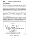
Three types
of
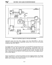
bus cycles define activity on the iPSB bus:.-
•
Arbitration Cycle - Determines the next owner
of
the bus. This cycle consists of a
resolution phase, in which competing bus agents determine priority for bus control,
and an acquisition phase, in which the agent with
the
highest priority initiates a
transfer cycle.
• Transfer
Cycle-
Performs a data transfer between the bus owner and another bus
agent. This cycle consists of a request phase, in which address control signals are
driven, and a reply phase, in which the two agents perform a handshake to
synchro-
nize the data transfer.
The
reply phase is repeated and data transfers continue until
the bus owner ends the transfer cycle.
,
•
Exception Cycle - Indicates that an exception (error) has occurred during a transfer
cycle. This cycle consists
of
a signal phase, in which an exception signal from one bus
agent causes all other bus agents to terminate any arbitration and transfer cycles in
progress, and a
reCQvery
phase, in which the. exception signals go inactive. A new
arbitration cycle can begin on the clock cycle after the recovery phase.
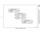
Figure
10-1
shows how the timing
of
these cycles overlap.
10-2