PHYSICAL DESIGN AND DEBUGGING
the transmission line from the source. The terminating' impedance combines with' the
destination input circuitry to produce a load that closely matches the characteristic
impedance of the line (board traces have characteristic impedances in the range of
30
ohms to
200
ohms).
The calculation of characteristic impedance
was
already discussed. Impedance of the
printed circuit board backplane connectors have
the impedance in the same range
as
the
traces (Le.,
30
to
200
ohms)
..
The characteristic impedance of a backplane may change, depending upon the length
of
the conductors or when using twisted pairs of co-axial cable in place of PC traces. Back-
plane impedance
is
also affected
by
the number of boards
plugg~d
into the backplane.
11.4.2.1.1 Need for Termination
The transmission line should be terminated when the tpd exceeds one-third of
tr
(rise
time).
If
the tpd <
1/3
tr, the line can be left unterminated, provided the capacitive
coupling between the traces does not cause cross-talk.
Termination thus eliminates impedance mismatches, increases noise immunity, sup-
presses
RFIIEMI, and helps to ensure that signals reach their destination with minimum
of distortion. There are
five
methods for terminating traces on the board:
1.
Series
2.
Parallel
3.
Thevenin
4.
AC.
5.
Active
Terminations can be costly, because they require additional components and power.
With passive terminations, extra drivers are needed
to
deliver more current to the line.
With active terminations extra power
is
needed which increases the power dissipation of
the system.
11.4.2.1.2 Series Termination
One way of controlling ringing on longer lines
is
with the series termination technique
also known
as
damping. This
is
accomplished by placing a resistor in series with the
transmission line at the driving device end. The receiver has no termination. The value
of the impedance looking into the driving device
(Rdriver
+
Ri
ine
=
Zo)
should approx-
imate the impedance of
the.
line
as
closely
as
possible.
In
this circuit the ringing dampens
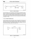
out when the reflection coefficient goes to zero. Figure
11-13
illustrates the series
termination.
11-17


