


I/O INTERFACING
For
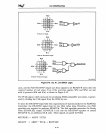
a cascaded interrupt request, the 82380 PIC will output an 8-bit cascade address on
the data bus during the first interrupt acknowledge cycle. A simple circuit can latch the
8-bit address and encode it to drive the CAS signals
(CAS2#-CASO#) of the slave
controllers. During the second interrupt acknowledge cycle, the
82380 will not drive the
data
bus; instead, the selected slave controller will
put
the interrupt vector on the
data
bus for the Intel386
DX
microprocessor.
Chapter 9 describes the interface to slave controllers that reside on a
MULTIBUS I
system bus.
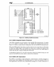
8.5.3 8259A Interrupt Controller
The 8259A Programmable Interrupt Controller
is
designed for use in interrupt-driven
microcomputer systems. A single 8259A can process up to eight interrupts. Multiple
8259As can be cascaded to accommodate up to
64
interrupts. A technique to handle
more than
64
interrupts
is
discussed at the end
of
this section.
The
8259A handles interrupt priority resolution and returns a preprogrammed service
routine vector to the InteI386
DX
microprocessor during an interrupt-acknowledge
cycle.
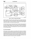
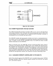
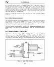
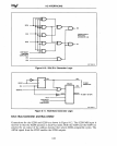
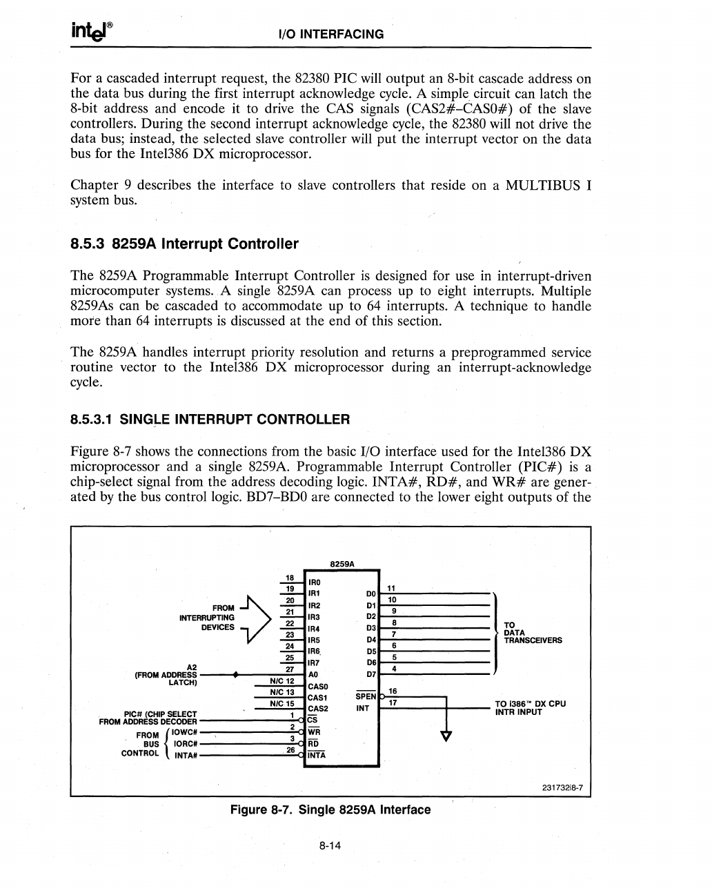
8.5.3.1 SINGLE INTERRUPT CONTROLLER
Figure 8-7 shows the connections from the basic I/O
interfaceused
for the InteI386
DX
microprocessor and a single 8259A. Programmable Interrupt Controller
(PIC#)
is
a
chip-select signal from the address decoding logic.
INTA#,
RD#,
and
WR#
are gener-
ated
by
the bus control logic. BD7-BDO are connected to the lower eight outputs of the
INTER
A2
(FROM
ADDRESS
LATCH)
PIC# (CHIP SELECT
FROM
ADDRESS
DECODER
FROM
{'OWC#
BUS
IORC#
CONTROL INTA#
8259A
~
IRO
~+
IRl
11
DO
10
FROM
~
IR2
01
9
RUPTING
-=-
IR3
02
DEVICES
-#-
03
8
IR4
-#-
04
7
IRS
~
IR6,
6
05
2L
06
5
IR7
27
07
4
AO
N/C 12
CASO
NIC 13
-
16
CASl
SPEN
N/C15
17
CAS2
INT
1
Cs
2
WR
3
AD
26
INTA
Figure 8-7. Single 8259A Interface
8-14
~7
I
TO
DATA
TRANSCEIVERS
TO
;386'·
ox
CPU
INTR
INPUT
231732i8·7